From Hashing to Scheduling: Why Meta Rebuilt Its AI Fabric
Meta’s AI training clusters have outgrown the traditional Clos-based IP fabrics that served earlier generations of workloads. The company’s Disaggregated Schedule Fabric (DSF) is its next-generation answer: a distributed, VOQ-based switching system designed specifically for the flow characteristics of large-scale distributed training. DSF is built on the open OCP-SAI standard and Meta’s FBOSS network operating system, and it is already running clusters that interconnect thousands of GPUs within a single data center region.
What Breaks in a Traditional Fabric
Training workloads that rely on remote direct memory access (RDMA) over UDP expose three distinct problems in a conventional IP fabric:
- Elephant flows: Long-duration, high-volume flows can saturate whatever links they hash onto, causing head-of-the-line blocking.
- Low entropy: Large collective operations may generate relatively few IP flows, leading to poor hashing distribution and congestion even when the fabric has idle capacity.
- Suboptimal utilization: The combination of the above produces significant skew in link bandwidth usage, forcing overprovisioning to maintain stable performance and tolerate failures.
Meta tested several mitigations before committing to a new architecture. BGP policies that pin traffic from leaf switches to a specific uplink based on destination solved steady-state entropy but degraded to equal-cost multipath (ECMP) routing during failures. Load-aware ECMP schemes handled fat flows but were hard to tune and introduced out-of-order packets, which is harmful to RDMA. A centralized traffic-engineering approach pre-computed flow patterns per model and programmed leaf switches pre-job; it worked for fat flows and low entropy but became unmanageable as the network scaled and reacted too slowly to failures.
Two Domains, One Virtual Switch
DSF’s core design separates the network into two domains. The Ethernet domain is where servers and standard networking protocols live. The fabric domain, by contrast, breaks packets into cells, sprays those cells across all available paths, and reassembles them in hardware before passing them back to the Ethernet domain.
The system is constructed from two hardware roles:
- Interface nodes (INs), also called rack disaggregated switches (RDSWs), handle external connectivity, routing, and interaction with the data center infrastructure.
- Fabric nodes (FNs), or fabric disaggregated switches (FDSWs), act as internal switching elements that move traffic at high speed across the fabric without needing Layer 3 routing.
To the outside world, the collection of INs and FNs presents as a single logical switch. The total external port count equals the sum of all ports across all INs, creating a virtual chassis that breaks the physical scaling limits of monolithic designs. The control plane, built on FBOSS, supports the multi-ASIC requirements of the disaggregated system; communication with the FBOSS State DataBase (FSBD) keeps state synchronized across nodes in real time.
Traffic management in DSF relies on packet spraying and a credit-based congestion control scheme, rather than hash-based load balancing. Ingress INs request credit tokens from egress INs, allowing scheduling decisions to react dynamically to path availability, congestion, and utilization. Virtual output queuing (VOQ) maintains lossless delivery: incoming packets are placed in per-destination, per-service-class queues that are scheduled independently. This yields near-optimal load balancing, effective use of full fabric bandwidth, and the ability to handle mixed traffic patterns without manual reconfiguration or traffic engineering.
Scaling From AI Zones to Regions
Meta has deployed DSF at three scales for GenAI training. The smallest building block is an AI zone, which contains multiple scaling units (SUs)—groups of GPU racks attached to RDSWs within the unit. All RDSWs in the AI zone connect through a common layer of FDSWs. The hardware split is notable: RDSWs run deep-buffer Jerico3-AI chips, while FDSWs use Ramon3 chips, with FBOSS as the operating system across all roles. Links between RDSWs and FDSWs are 2x400G FR4 optics. GPU-to-RDSW connections are rail-optimized, which benefits latency-sensitive hierarchical collectives like allreduce and allgather.
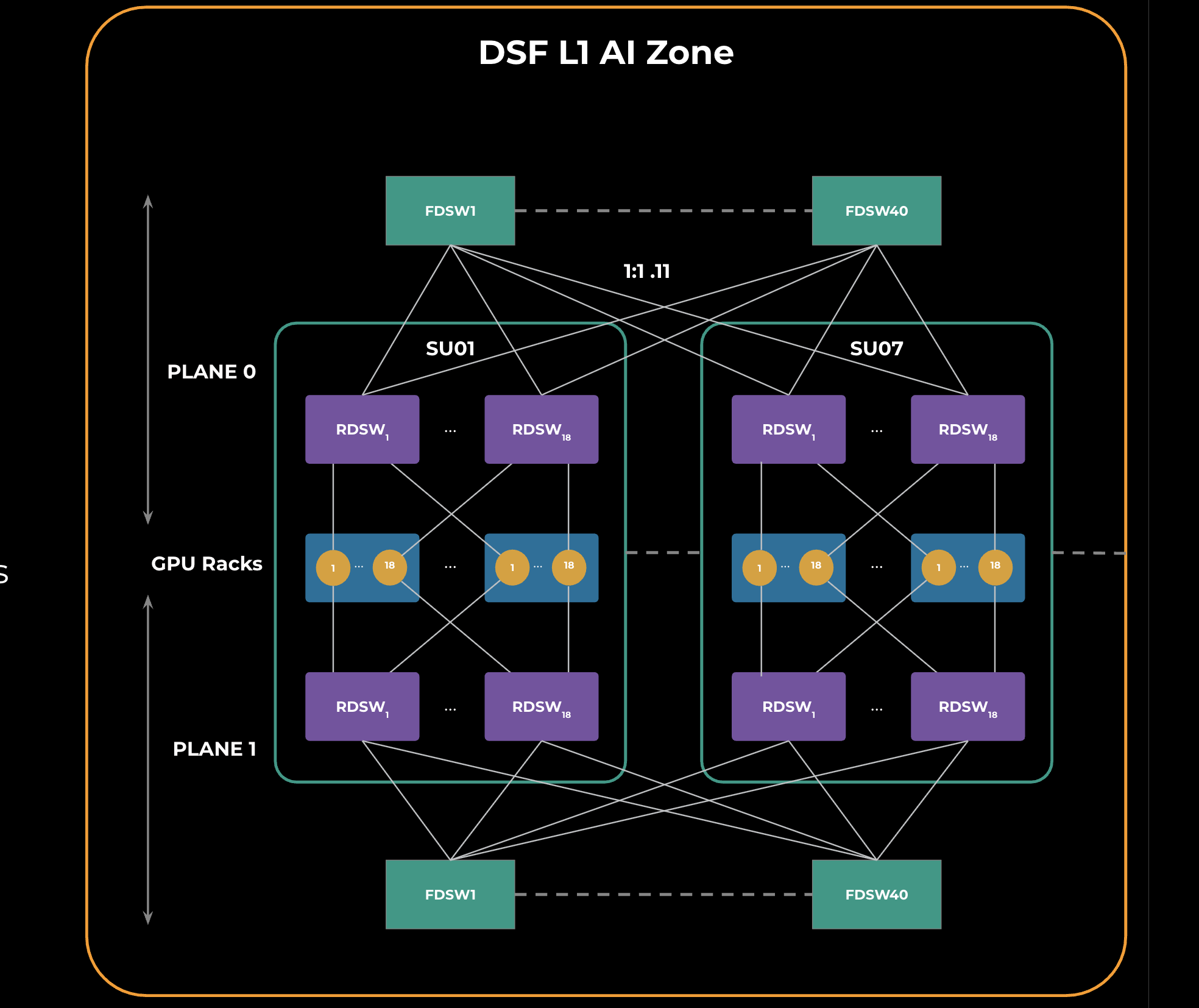
Two identical network planes make up a DSF L1 zone, which serves as the basic unit for larger clusters.
The next tier, DSF L2, interconnects 4x L1 zones through a second stage of spine DSF switches (SDSWs). SDSWs reuse FDSW hardware and make the four L1 zones behave as a single, non-blocking fabric at a scale of 18K x 800G GPUs.
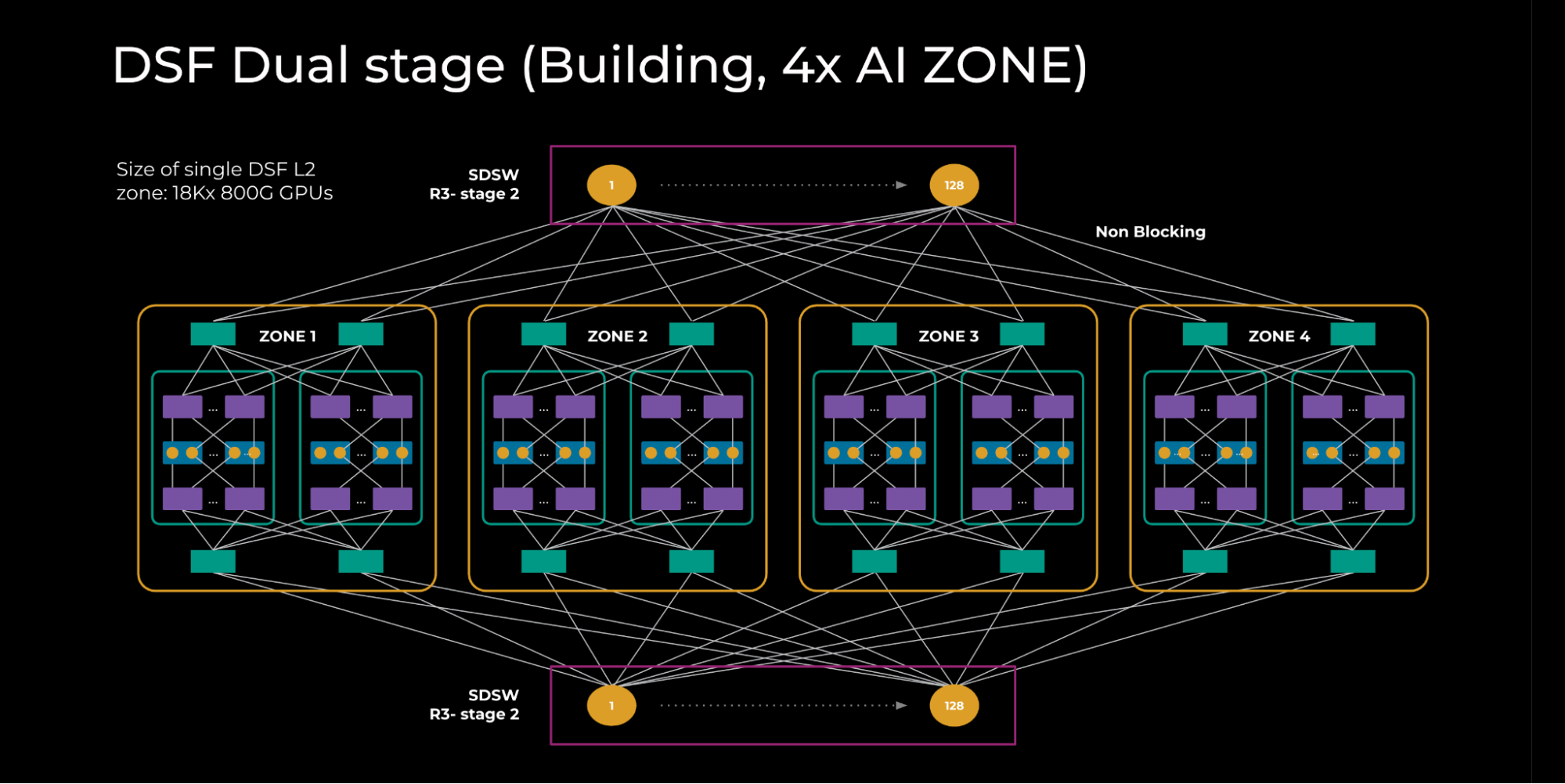
All RDSWs in this topology maintain fully meshed FDSB sessions to exchange IPv6 neighbor state. An input-balanced mode is enabled to distribute reachability information across the layers so that failures do not cause congestion on the fabric or spine layers.
The largest deployment, a DSF region, connects 5x L2 zones through an L3 super-spine layer. Each building contributes a special edge point of delivery (PoD) made of 40 FDSWs and 128 edge DSF switches (EDSWs). EDSWs use the same hardware as RDSWs but serve a distinct purpose: providing connectivity to the L3 super spine. Each EDSW links to four superspine devices with 4x800G links, yielding 2K x 800G ports per edge PoD.
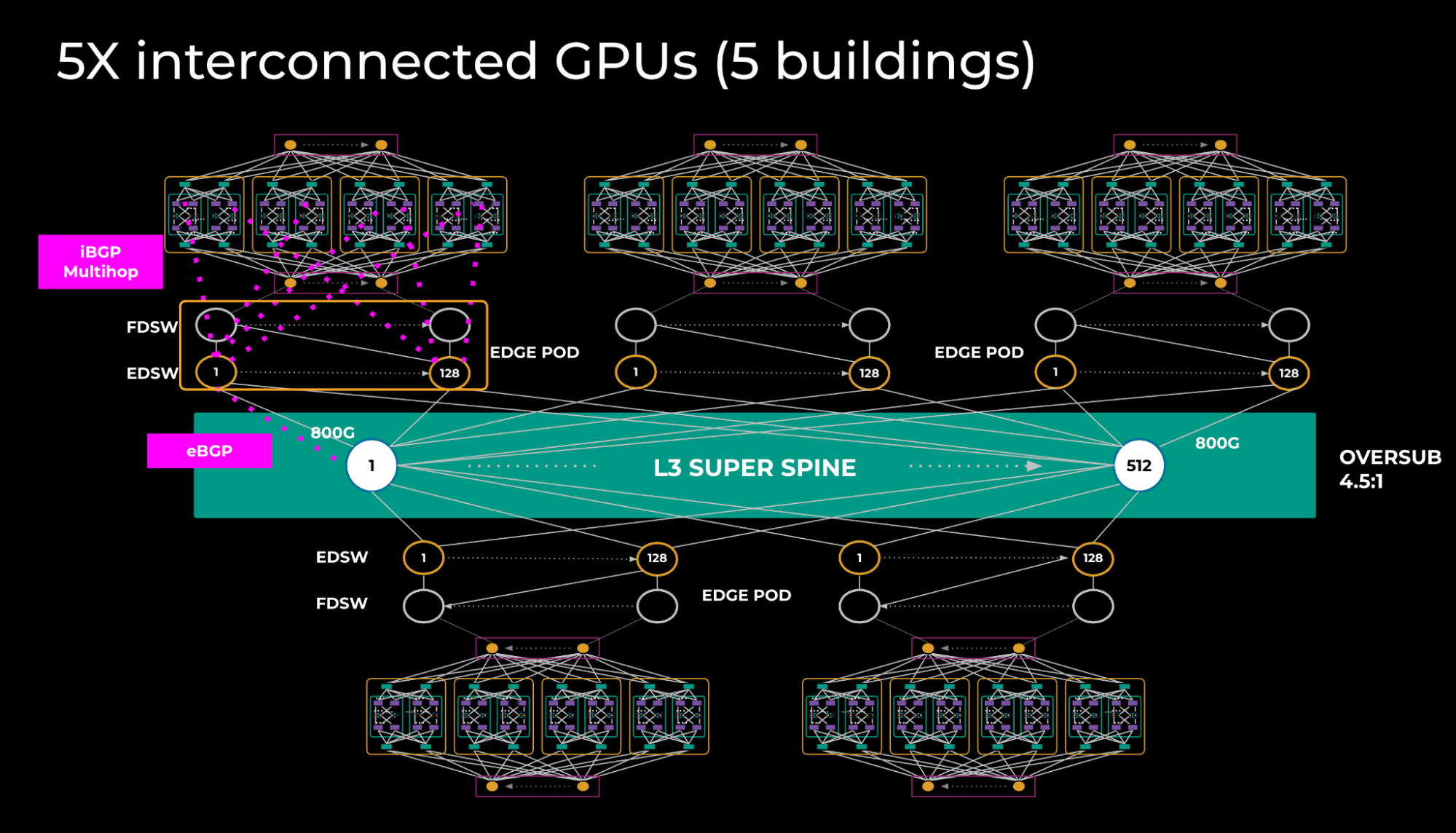
Because of how training models are sharded, relatively little traffic crosses the L3 tier, so an oversubscription ratio of 4.5:1 is acceptable. On the L3 interconnect, iBGP sessions are established between EDSWs and all RDSWs within the building, with BGP add-path enabled so that RDSWs learn aggregates via all 2K next-hops. Between EDSWs and the L3 super spine, eBGP is used, and only aggregate routes are exchanged over the peerings.
The L3 spine reintroduces some of the entropy and fat-flow problems seen in traditional fabrics, but at this tier traffic volumes are far lower, making those issues much less significant.
How Input Balanced Mode Reacts to Link Failures
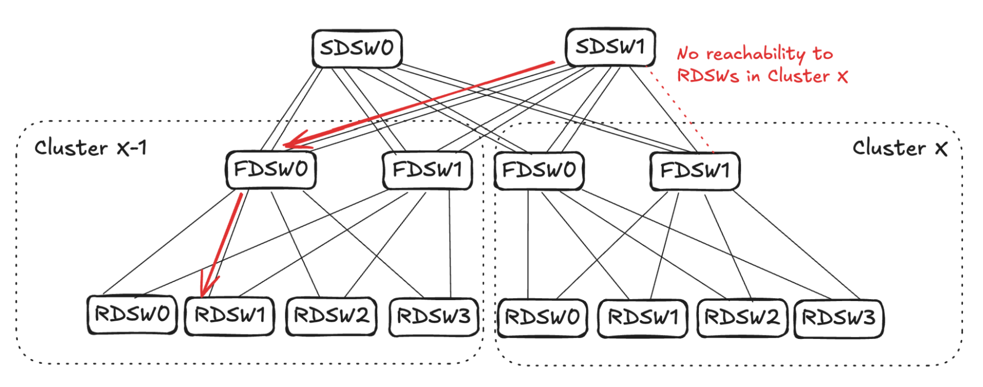
Input Balanced Mode is designed to keep traffic balanced across the DSF network when remote link failures occur. Its core guarantee: no DSF device should ever have more input bandwidth than output bandwidth. That means no oversubscription, even after a link goes down. When a device loses a link, it propagates reduced reachability information across the cluster so other devices know to send proportionally less traffic its way.
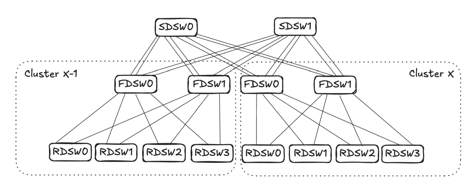
Note: For clarity, in the figures above, FDSW/SDSW are simplified to show one virtual device each. The examples below illustrate two distinct link-failure scenarios and how the fabric reacts to each.
When an RDSW-to-FDSW Link Fails
If an RDSW-to-FDSW link fails, the RDSW loses both input and output capacity on that link. The FDSW also loses connectivity to the RDSW and stops advertising it. In the example, FDSW1 in Cluster X loses its connection to RDSW3, so it stops advertising reachability to SDSW0 and SDSW1.
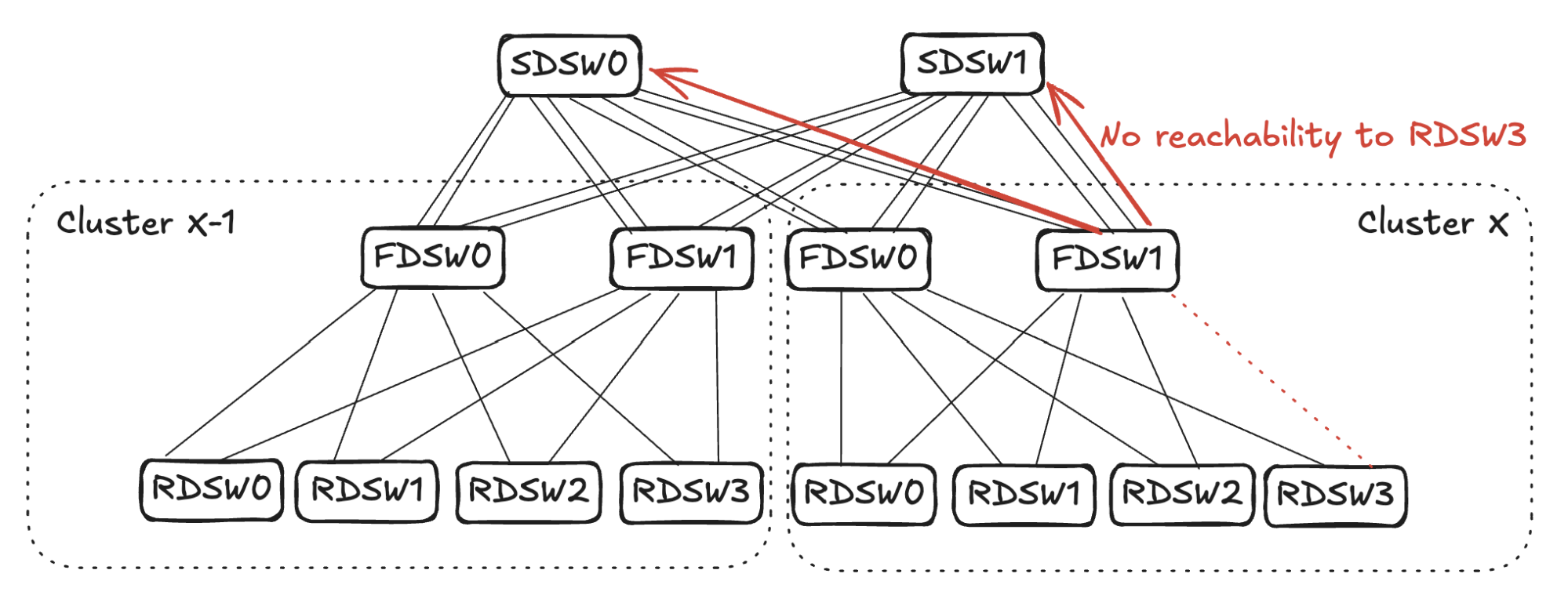
From SDSW0's perspective, it still has reachability to RDSW3 through FDSW0 in Cluster X, even though FDSW1 no longer advertises it. But now the input capacity toward RDSW3 is 4 (FDSW0 and FDSW1 in Cluster X-1), while output capacity is only 2 (FDSW0 in Cluster X). To avoid oversubscription, SDSW0 picks two input links and stops advertising reachability toward RDSW3 in Cluster X. SDSW1 performs the same sequence.
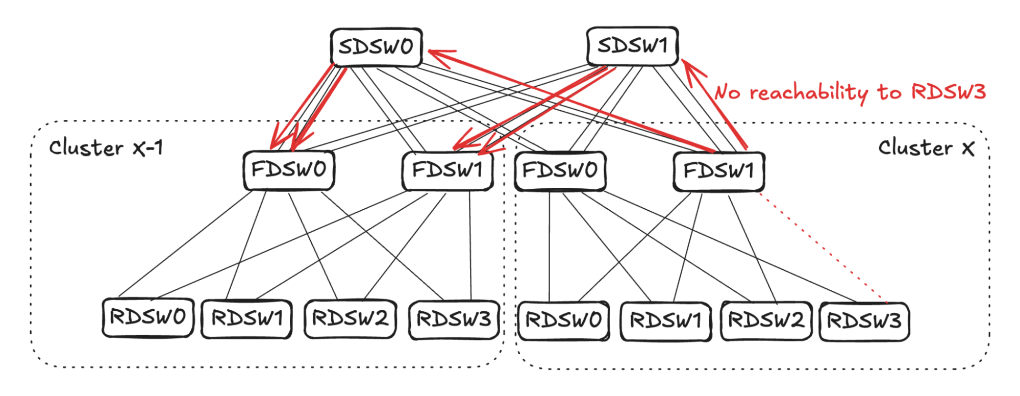
Link selection in Input Balanced Mode must be randomized. In the example, SDSW0 stops advertising reachability to FDSW0, and SDSW1 stops advertising to FDSW1. Each FDSW now has input capacity of 4 and output capacity of 2, so each randomly selects two links to stop advertising.
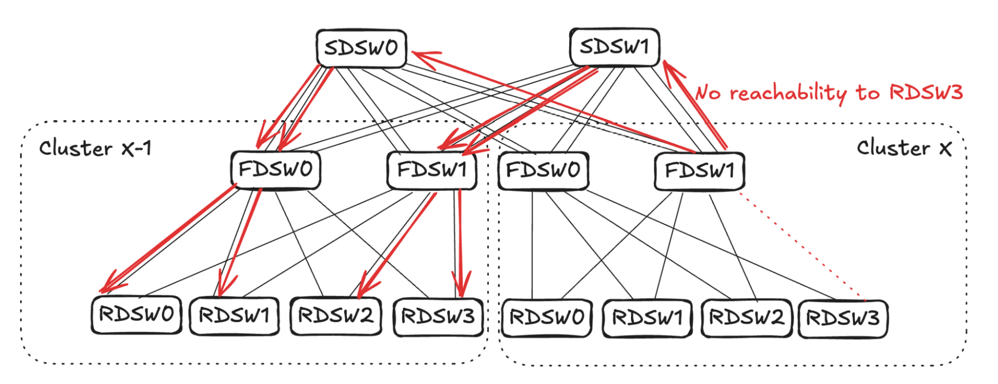
If FDSW0 randomly picks its links to RDSW0 and RDSW1, and FDSW1 picks links to RDSW2 and RDSW3, the propagation completes. Each RDSW in Cluster X-1 ends up with 50% capacity to forward traffic toward RDSW3 in Cluster X.
When an FDSW-to-SDSW Link Fails
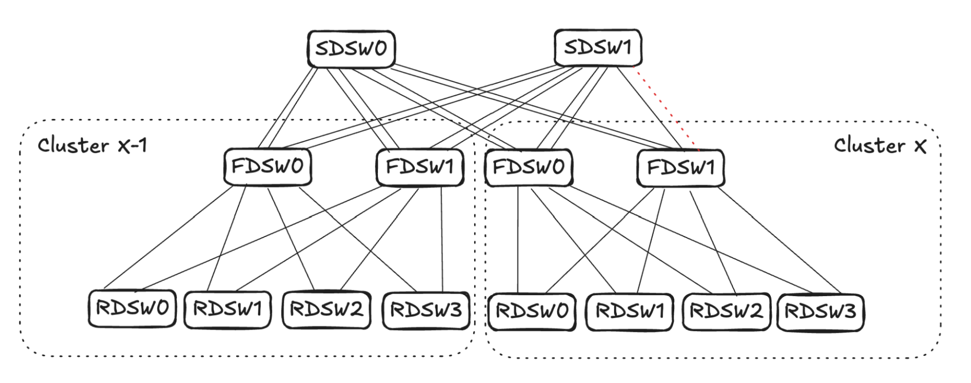
An FDSW-to-SDSW link failure requires propagation in two directions: on the FDSW side, reduce input capacity from RDSWs; on the SDSW side, reduce input capacity from FDSWs in other clusters.
Propagation on the FDSW Side
Consider traffic egressing Cluster X through FDSW1. From FDSW1's view, input capacity is 4 (from RDSW0-RDSW3), but output capacity has dropped to 3 due to the failed link. To balance input, FDSW1 randomly picks one FDSW-to-RDSW link and stops advertising reachability to all destinations outside the cluster.
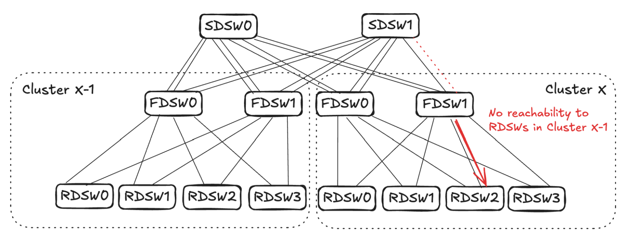
If FDSW1 in Cluster X picks its link to RDSW2, it stops advertising reachability to all RDSWs in Cluster X-1 over that link. The link remains usable for intra-cluster traffic, since it still has full reachability within Cluster X.
Propagation on the SDSW Side
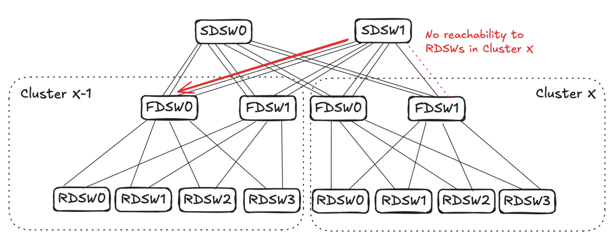
For traffic ingressing Cluster X through SDSW1, input capacity is 4 (from FDSW0 and FDSW1 in Cluster X-1), while output capacity is 3 after the link failure. SDSW1 randomly picks one link toward Cluster X-1 and stops advertising reachability to all RDSWs in Cluster X. FDSW0 in Cluster X-1 performs the same calculation: it picks one link and stops advertising reachability to all RDSWs in Cluster X. That completes propagation, leaving RDSW1 in Cluster X-1 with one fewer link for forwarding traffic toward Cluster X.
Simultaneous FDSW-to-SDSW and RDSW-to-FDSW Failures
When link failures occur in both segments at once, the reduced reachability propagates and converges in both directions:
- FDSW-to-SDSW link failure.
- RDSW-to-FDSW link failure.
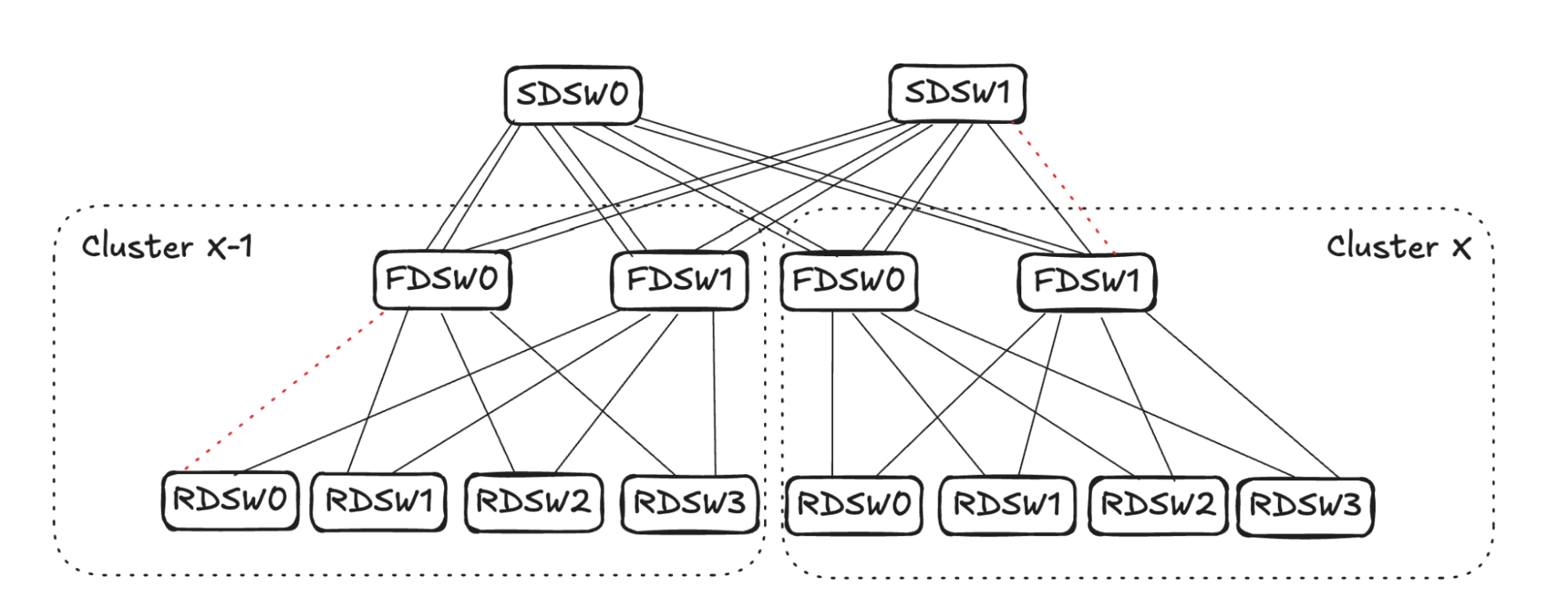
Propagation from the FDSW-to-SDSW Failure
For the FDSW-to-SDSW failure, FDSW1 in Cluster X randomly picks one connected RDSW and stops advertising reachability toward Cluster X-1 devices.
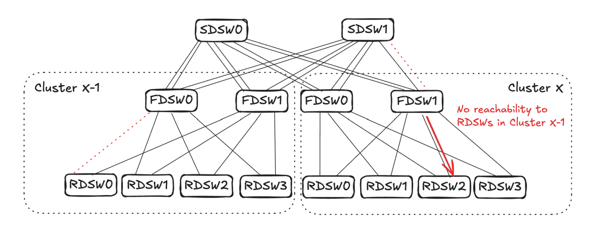
Similarly, SDSW1 randomly picks one link toward Cluster X-1 and propagates no reachability to Cluster X. If SDSW1 picks a link toward FDSW0 in Cluster X-1, note that FDSW0 already has a link failure to RDSW0. Its input and output capacity toward Cluster X are already balanced, so propagation stops in that direction.
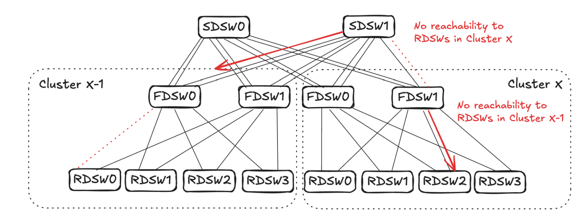
Propagation from the RDSW-to-FDSW Failure
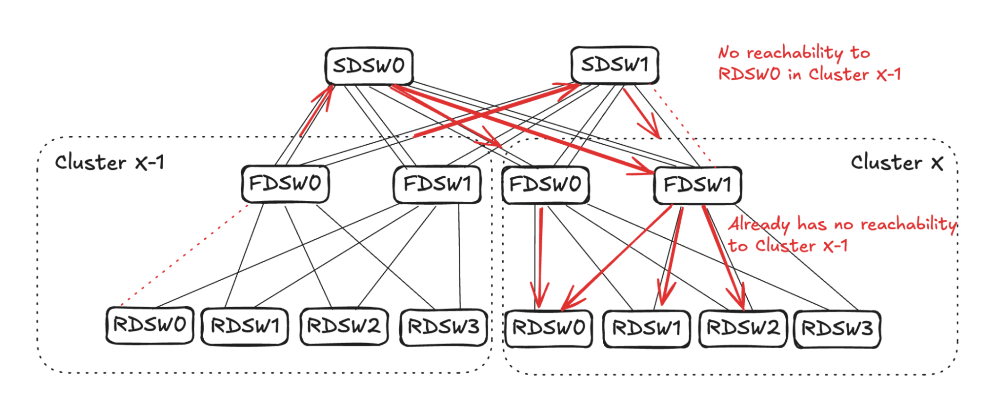
When FDSW0 in Cluster X-1 loses connectivity to RDSW0, it stops advertising reachability to SDSW0 and SDSW1 on both of its links. SDSW0 then randomly picks two links to stop advertising reachability to RDSW0 in Cluster X-1 — in the example, one link on FDSW0 and one on FDSW1. SDSW1, already affected by one link failure to FDSW1 in Cluster X, only needs to pick one additional link; in the example it picks the other link toward FDSW1.
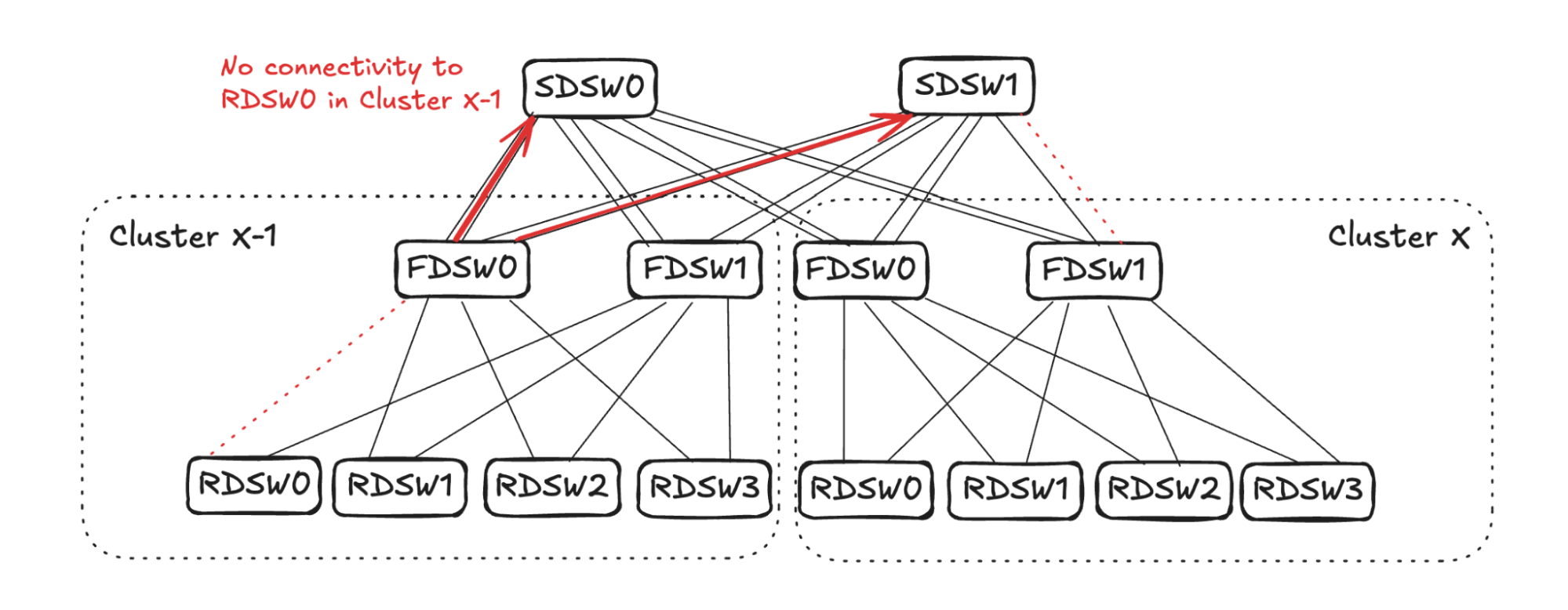
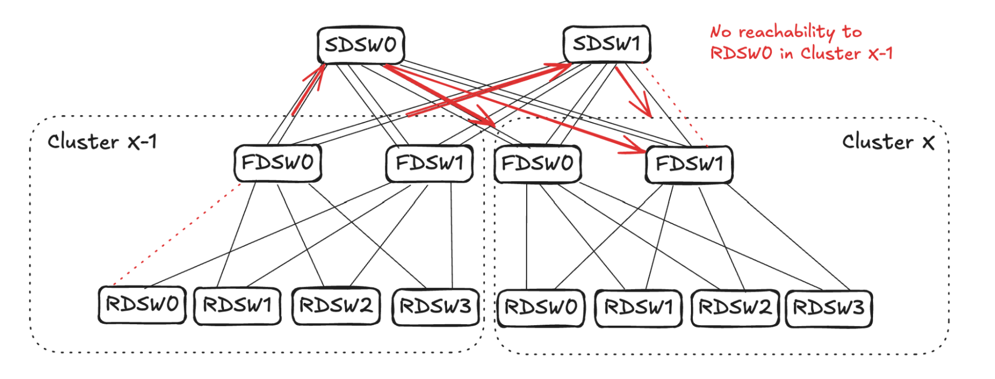
From Cluster X FDSW1's perspective, output capacity toward RDSW0 in Cluster X-1 is 1 — two links with no reachability plus one link failure. To balance input, it selects three links to stop advertising reachability toward RDSW0 in Cluster X-1. One of those links (FDSW1-to-RDSW2) already has no reachability toward Cluster X-1 from the earlier FDSW-to-SDSW propagation. So FDSW1 picks two additional links (RDSW0 and RDSW1 in the example). Cluster X FDSW0 randomly picks one downlink (RDSW0) to stop advertising reachability to RDSW0 in Cluster X-1.
Next Steps for DSF
- Meta is interconnecting multiple regions to create mega clusters, extending GPU interconnectivity across regions tens of kilometers apart.
- That introduces heterogeneity challenges: different GPU types and fabrics spanning different regions.
- A new technology called Hyperports will combine multiple 800G ports at the ASIC level to act as a single physical port, reducing the impact of fat flows on IP interconnects.
DSF inherently supports a wide range of GPUs and NICs. Deployments are expanding to include an increasing variety of GPU and NIC models.