

From Sketch To Working System
Intent Prototyping starts with a simple premise: give an AI model everything it needs to understand what you are designing, not just what it should look like. You feed it your rough screen sketches, a description of the conceptual model, and user flow diagrams. It then assembles those inputs into a fully interactive, testable prototype.
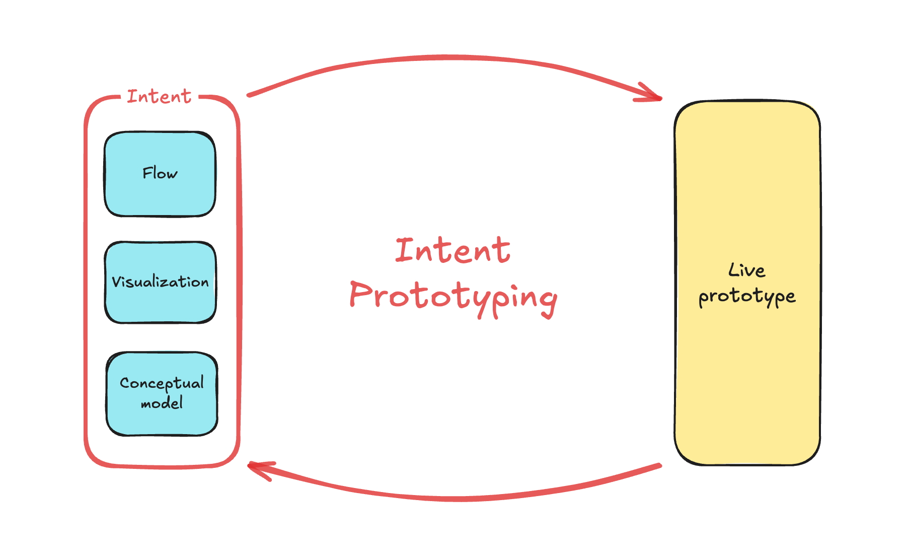
This process addresses the vulnerabilities of traditional methods by changing what the prototype actually is:
- It is a living product, not a drawing. Because it is interactive, a vast set of realistic data can be loaded into it. As a result, you evaluate the entire application logic and the underlying model of the system, going far beyond the pixel-level validation offered by static mockups.
- It eliminates the guessing game. As opposed to the chaos of vibe coding, the construction adheres to a precise specification. Development receives clarity, not a puzzle. They inherit both the functional code as well as a transparent, documented record of the design’s intent. No one has to reverse engineer how the design should behave or spend time on code archaeology.
The consequence is a process crafted for high-stakes enterprise software. It forces early evaluation of the system’s real breaking point: the foundational information architecture and logic, doing so with incredible speed. But it is not a one-shot deployment. Because the input is fluid, you can change the blueprint at any moment to test alternative directions, adapting the prototype continuously to user feedback as it arrives. That level of focused iteration makes the expensive, rigid workflow of the past obsolete.
Turning A Rough Sketch Into A Working Prototype
To show how this works in practice, let’s follow a concrete case: a simple tool for tracking tests that validate product ideas. The complete project, including all source code and documentation, is available in this GitHub repository.
The process begins before any real design work. After proper research, a vague idea starts to take shape — and the key is to capture it immediately, while it is still rough. Visual polish is irrelevant at this stage; the goal is to move from that first messy sketch straight to a live prototype for user testing, not to perfect the drawing.
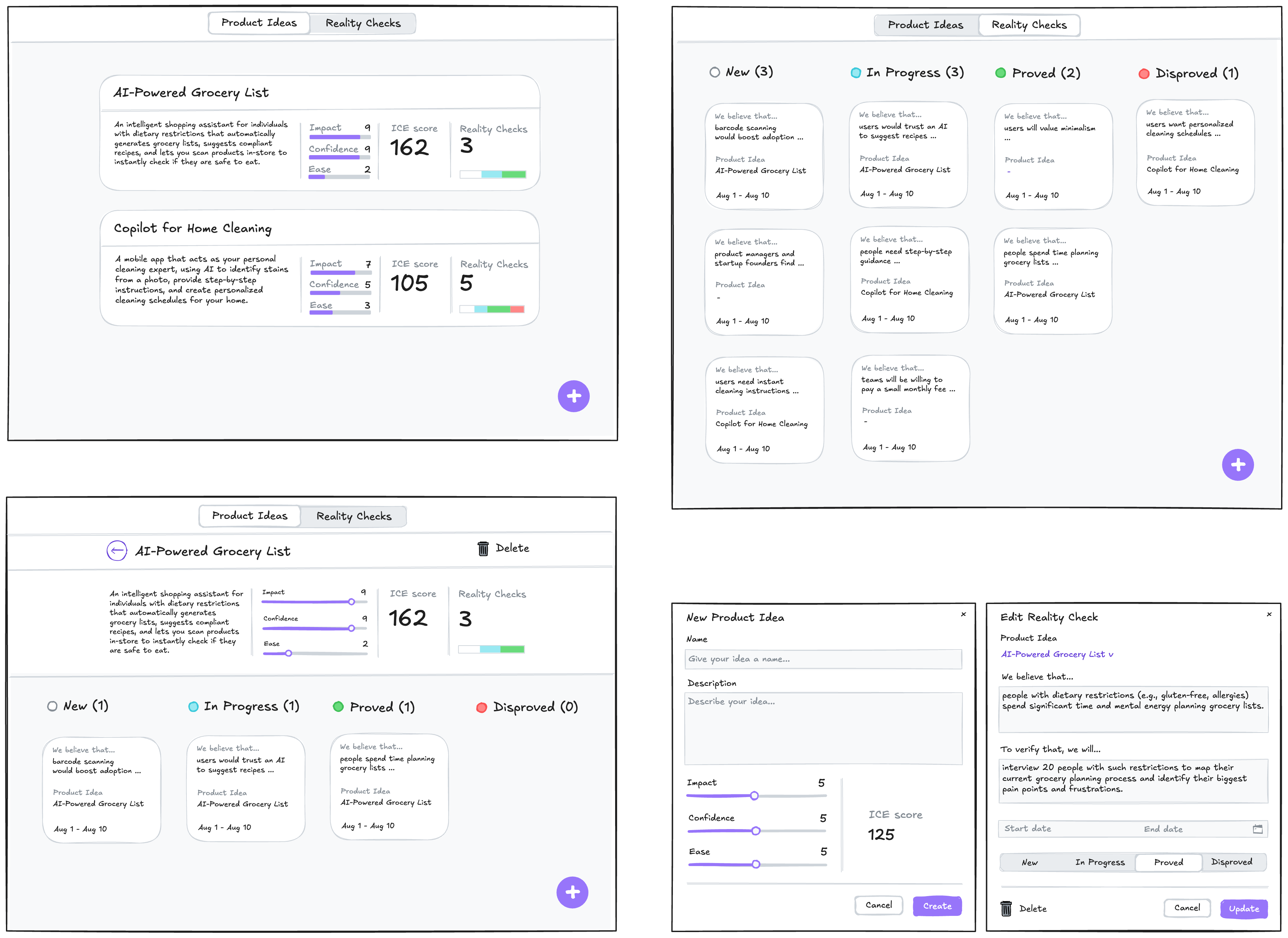
The drawing tool itself (Excalidraw was used here) does not matter. What matters is adding just enough detail for the sketch to serve as usable input for a junior frontend developer — or, in this case, for an AI assistant. The annotations must cover:
- Navigational paths — what clicking an element leads to.
- Dynamic behavior that static images cannot show: scroll restrictions, responsive layout, drag-and-drop.
- Which parts should be reusable components.
- Which design system components to use (here, the Ant Design Library).
- Any further comments on how the thing should function, as opposed to how it should look.
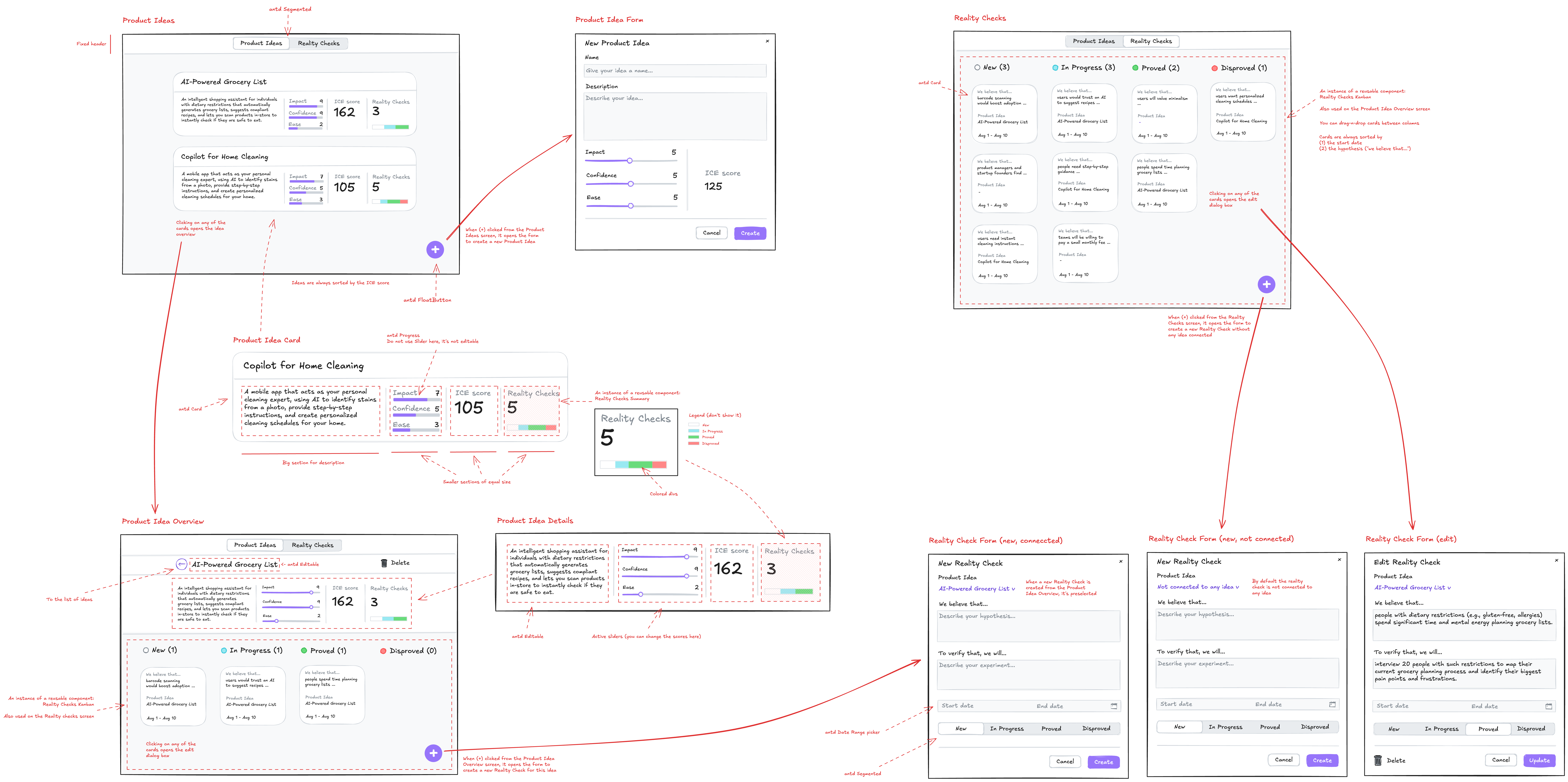
That annotated sketch captures both Visualization and Flow, but it still lacks the Conceptual Model — the objects, their attributes, and their relationships. Without it, the expression of intent is incomplete. For more complex applications you might draw this as a UML class diagram in the sketch margins, but here it is simpler to ask a multimodal LLM to derive a textual description of the model from the sketch itself.
Gemini 2.5 Pro is a good fit for this one-off task because it accepts both text and image input (GPT-5 and Claude-4 also qualify). Google AI Studio provides the control and visibility needed for this kind of work.
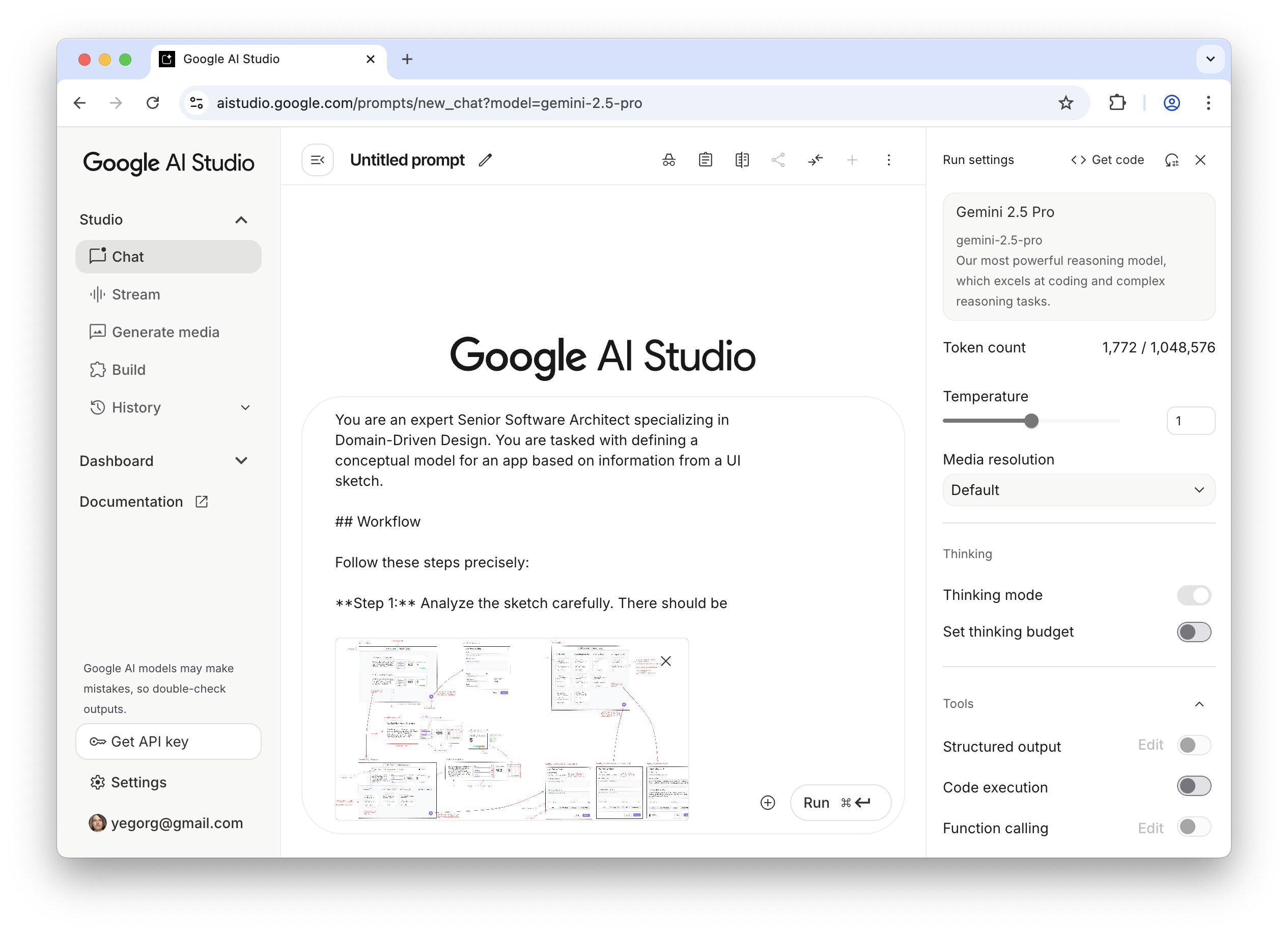
Note: Every prompt used here is listed in the Appendices. They are not project-specific and can be reused as-is.
The output is both a written description and a diagram:
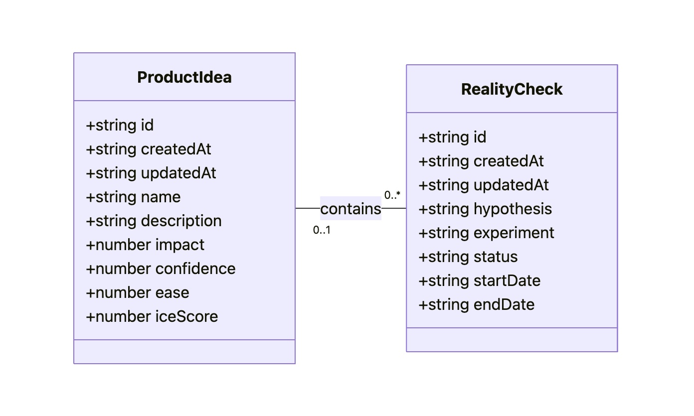
That diagram may look technical, but a clear grasp of all objects, attributes, and relationships is what separates solid design from guesswork. Along with Flow and Visualization, the Conceptual Model is an essential part of expressing intent.
After this step, intent is fully captured in just two files: Sketch.png and Model.md. These become the durable source of truth for everything that follows.
From Intent To Implementation
The second step produces a technical specification and a step-by-step plan, with AI doing the bulk of the work and a human keeping watch. The Data Access Layer and the UI are specified separately using two different prompts — the output of the first feeds into the second — and both are guided by prototyping-specific guidelines that are not tied to this project.
The result is content for DAL.md and UI.md. The LLM output is generally reliable, but it deserves scrutiny. You don’t need to be a programmer to review it, though some programming literacy helps. If something is unclear, ask the LLM before refreshing the context window; if you spot a mistake, point it out and it will fix or justify its approach.
A crucial caveat: LLMs are not deterministic and can miss small details, particularly those hidden in sketches. For instance, a “Delete” button in the sketch’s upper right corner might never make it into the spec. No expertise is required to catch such omissions — just mention them and move on.
Once Sketch.png, Model.md, DAL.md, and UI.md exist and have passed review, the technical design is complete. It provides a stable foundation for building without drifting from the original intent. The final touch is a step-by-step plan, split into one part for the Data Access Layer and another for the UI.
Executing that plan requires a different category of tool. Up to this point, generative AI sufficed for one-off content creation. But building a prototype from multi-file specs and a sequenced plan requires an agentic AI that can maintain coherence across multiple files and execute tasks in order. Expecting a simple generative AI to handle this would be like showing a person only a single brick and expecting a house.
Google Gemini CLI is the coding agent used here, since Gemini 2.5 Pro already performs well and no middleman (Cursor, Windsurf) is needed. Claude Code would be the natural equivalent for Claude users, and the same process should work with any preferred tool having similar capabilities.
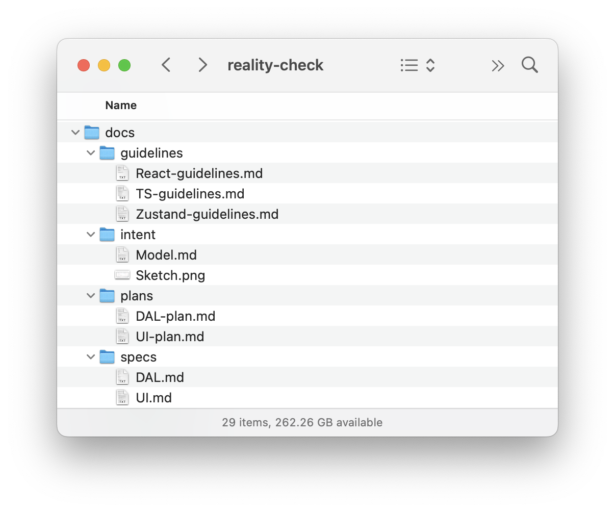
Before delegating to the agent, scaffold a basic React template with Vite — standard tutorials cover this. Then place all documentation files into the project:
Open the terminal in the project folder and launch “gemini”:
Send the Data Access Layer build prompt, which implies step-by-step execution; after each step, confirm the result:
Thank you! Now, please move to the next task.
Remember that you must not make assumptions based on common patterns; always verify them with the actual data from the spec.
After each task, stop so that I can test it. Don’t move to the next task before I tell you to do so.
As the final task in the plan, the agent builds a dedicated test page for the Data Access Layer so it can be manually verified:
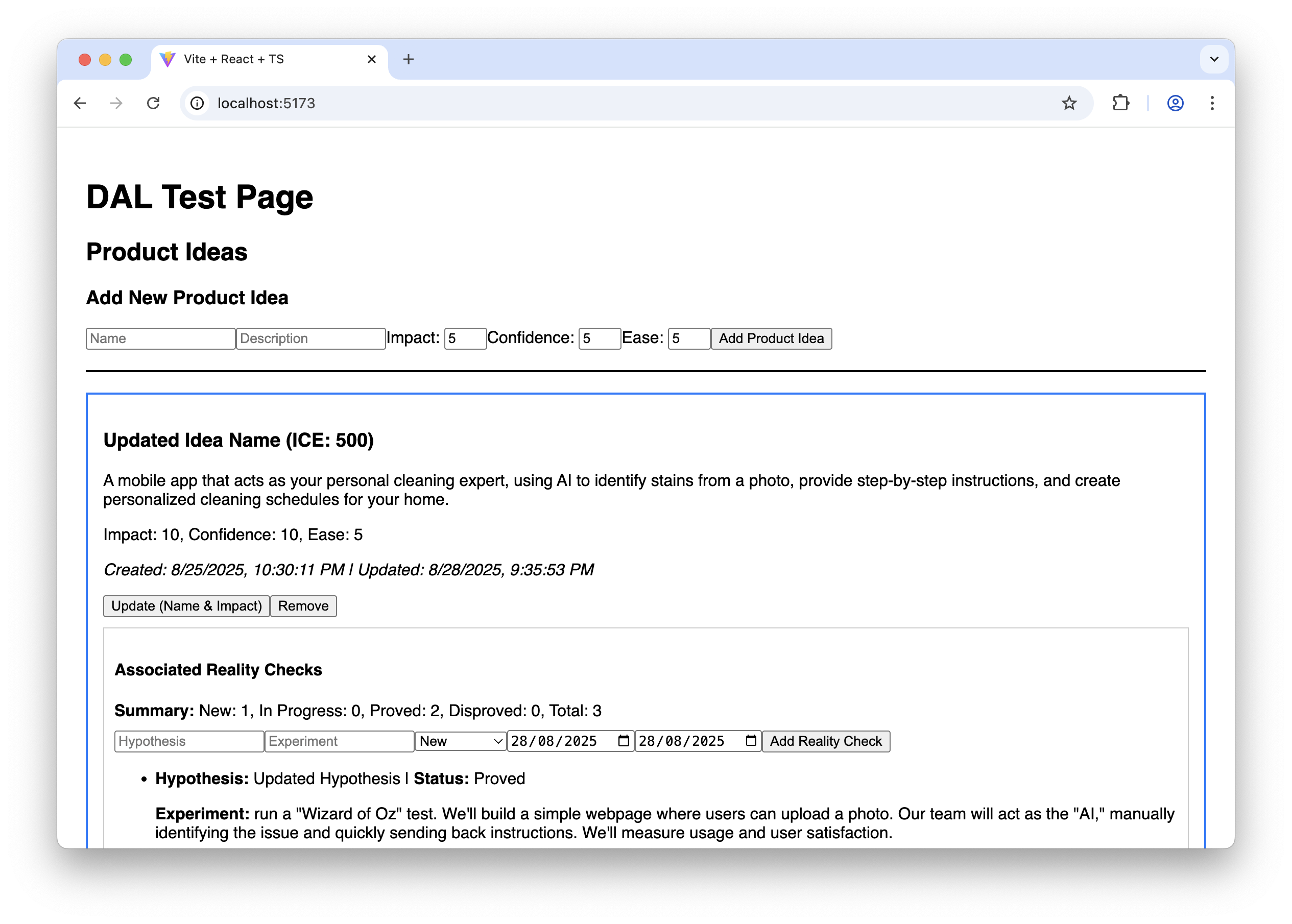
It may not win design awards, but it confirms the layer works before the real UI is built. Then the context window is cleared and the UI build prompt is sent in a fresh session. Each step gets manual testing per the plan, and since attention to visual detail is still a weakness of LLMs, a few nudges are usually needed at each stage:
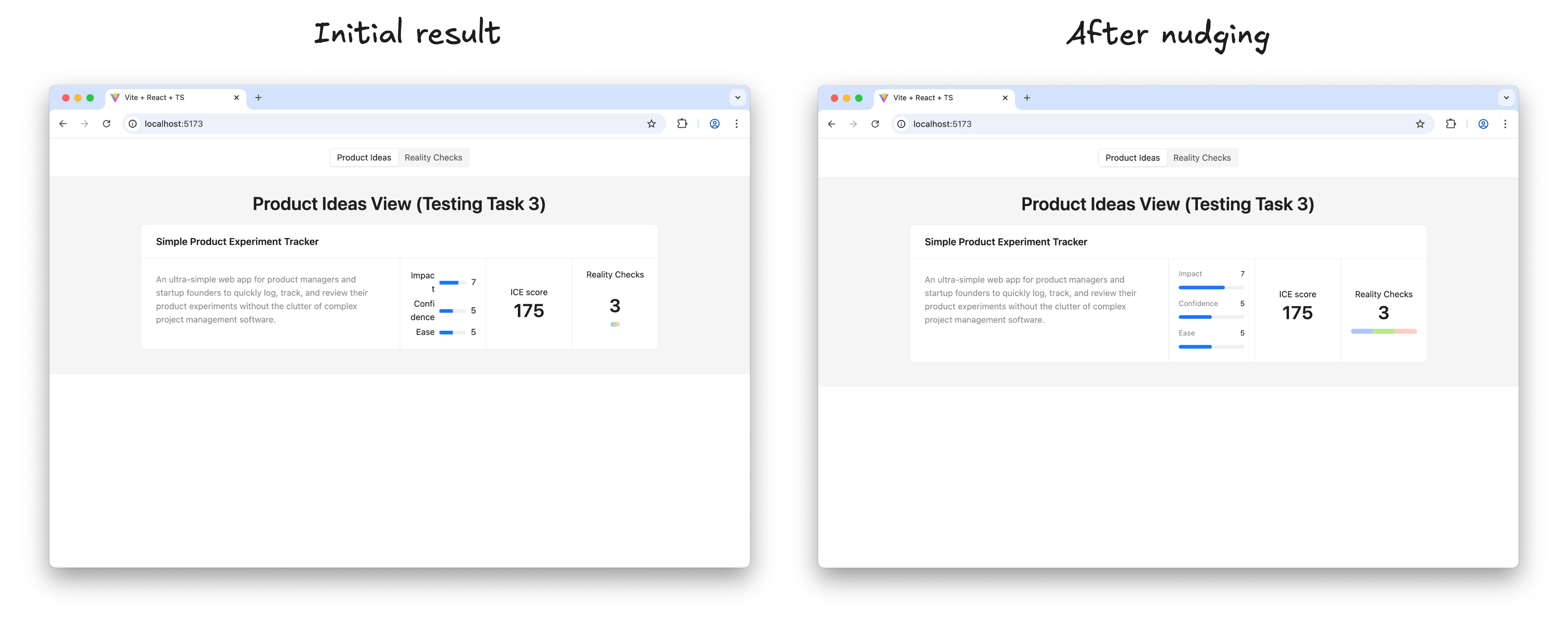
When a step meets expectations, the agent is told to proceed:
Thank you! Now, please move to the next task.
Make sure you build the UI according to the sketch; this is very important. Remember that you must not make assumptions based on common patterns; always verify them with the actual data from the spec and the sketch.
After each task, stop so that I can test it. Don’t move to the next task before I tell you to do so.
Before long, the result looks right and behaves exactly as intended:
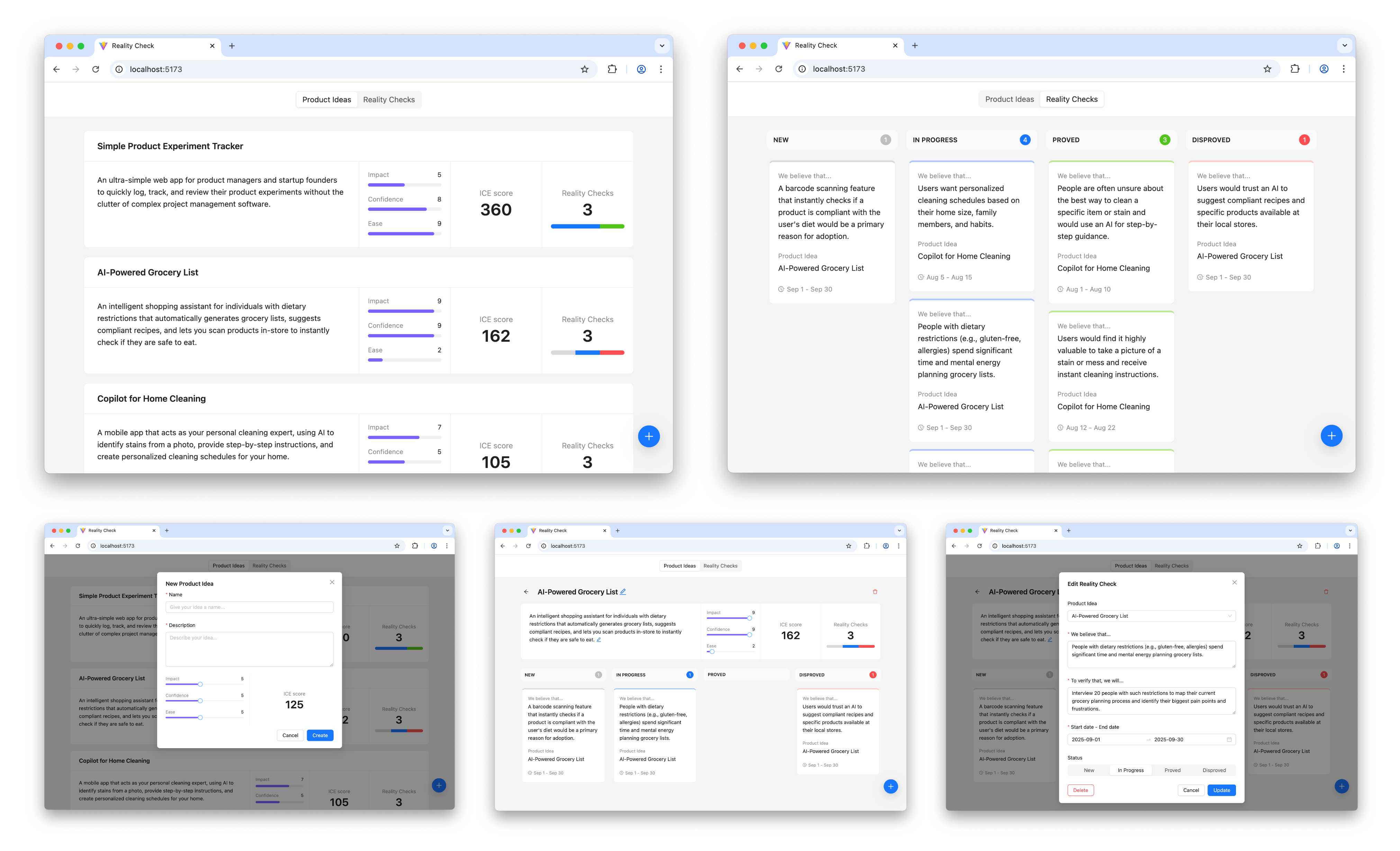
The working prototype is not the end of the road — the interesting part is only beginning.
Iteration And Weight
Now the prototype goes in front of potential users to learn whether it actually relieves their pain. Each lesson triggers a new iteration: update sketches and the conceptual model, revise the specifications, create a fresh plan, and execute it. Every cycle repeats the same four steps.
Is This Too Heavy?
The workflow may sound like a lot of upfront thinking that could stifle creativity. Before writing it off, weigh these points:
- Only the first step (expressing intent) and the last (learning from users) demand real effort from a human. AI does nearly everything in between, with light oversight.
- Iterations can be deliberately small. Start with a Walking Skeleton — the thinnest possible implementation — and add substance later. Direction can change between iterations.
- “Think before you do” is not automatically bad. A clear, unambiguous statement of intent prevents mistakes and saves effort downstream.
Where Intent Prototyping Fits
No single method fits every situation, and Intent Prototyping is no exception. Strong teams pick the tool that mitigates the biggest current risk. The comparison below lays out how common methods and tools differ in their primary goals and the risks they mitigate.
| Method/Tool | Goal | Risks it is best suited to mitigate | Examples | Why |
|---|---|---|---|---|
| Intent Prototyping | To rapidly iterate on the fundamental architecture of a data-heavy application with a complex conceptual model, sophisticated business logic, and non-linear user flows. | Building a system with a flawed or incoherent conceptual model, leading to critical bugs and costly refactoring. |
| It enforces conceptual clarity. This not only de-risks the core structure but also produces a clear, documented blueprint that serves as a superior specification for the engineering handoff. |
| Vibe Coding (Conversational) | To rapidly explore interactive ideas through improvisation. | Losing momentum because of analysis paralysis. |
| It has the smallest loop between an idea conveyed in natural language and an interactive outcome. |
| Axure | To test complicated conditional logic within a specific user journey, without having to worry about how the whole system works. | Designing flows that break when users don’t follow the “happy path.” |
| It’s made to create complex if-then logic and manage variables visually. This lets you test complicated paths and edge cases in a user journey without writing any code. |
| Figma | To make sure that the user interface looks good, aligns with the brand, and has a clear information architecture. | Making a product that looks bad, doesn't fit with the brand, or has a layout that is hard to understand. |
| It excels at high-fidelity visual design and provides simple, fast tools for linking static screens. |
| ProtoPie, Framer | To make high-fidelity micro-interactions feel just right. | Shipping an application that feels cumbersome and unpleasant to use because of poorly executed interactions. |
| These tools let you manipulate animation timelines, physics, and device sensor inputs in great detail. Designers can carefully work on and test the small things that make an interface feel really polished and fun to use. |
| Low-code / No-code Tools (e.g., Bubble, Retool) | To create a working, data-driven app as quickly as possible. | The application will never be built because traditional development is too expensive. |
| They put a UI builder, a database, and hosting all in one place. The goal is not merely to make a prototype of an idea, but to make and release an actual, working product. This is the last step for many internal tools or MVPs. |
The guiding principle: every method is a specialized tool for a specific risk type. Figma removes risk from visual presentation; ProtoPie de-risks the feel of an interaction. Intent Prototyping uniquely targets the most foundational risk in complex applications — building on a flawed or incoherent conceptual model.
The Bigger Trade-Off
For years, a common failure in product design has been the “lopsided horse”: a polished exterior that hides a weak, unworkable foundation. This is the inevitable result of choosing between visual fidelity and structural flexibility. When you focus on the surface, you lose sight of how the system actually behaves. Intent Prototyping, supported by modern AI, removes that false dilemma. It reframes the workflow around a precise intent, cutting redundant work and shifting energy toward building a dependable, coherent architecture.
This approach yields three concrete advantages. Foremost, jumping straight to live, interactive models means user testing validates the logic of the system, not just its appearance, right from the start. Second, writing down the intent forces a level of clarity that prevents fuzzy thinking about the underlying mechanics. Third, that written intent becomes a permanent reference point. It removes messy handoffs where engineers are left guessing what a designer meant from a static image, wiping out the redundant and error-prone task of reverse-engineering a vision.
Essentially, Intent Prototyping alters the deliverable. Teams stop producing images of a product and instead create blueprints for a system. With AI handling the heavy lifting, a live prototype can become the main workspace for ideation, rather than a costly final step.
All the Pieces
A complete Intent Prototyping Starter Kit is available in a GitHub repository. This includes the full set of prompts, guidelines, the example used here, and a minimal boilerplate project to get started.
The appendices detail each stage of the workflow:
- Appendix 1: Sketch to UML Class Diagram
- Appendix 2: Sketch to DAL Spec
- Appendix 3: Sketch to UI Spec
- Appendix 4: DAL Spec to Plan
- Appendix 5: UI Spec to Plan
- Appendix 6: DAL Plan to Code
- Appendix 7: UI Plan to Code
- Appendix 8: TS-guidelines.md
- Appendix 9: React-guidelines.md
- Appendix 10: Zustand-guidelines.md
Each of these steps is demonstrated with concrete examples from the article, which you can review to see the full arc from a rough sketch to working code.
You are an expert Senior Software Architect specializing in Domain-Driven Design. You are tasked with defining a conceptual model for an app based on information from a UI sketch.

## Workflow

Follow these steps precisely:

**Step 1:** Analyze the sketch carefully. There should be no ambiguity about what we are building.

**Step 2:** Generate the conceptual model description in the Mermaid format using a UML class diagram.

## Ground Rules

- Every entity must have the following attributes:
    - `id` (string)
    - `createdAt` (string, ISO 8601 format)
    - `updatedAt` (string, ISO 8601 format)
- Include all attributes shown in the UI: If a piece of data is visually represented as a field for an entity, include it in the model, even if it's calculated from other attributes.
- Do not add any speculative entities, attributes, or relationships ("just in case"). The model should serve the current sketch's requirements only.
- Pay special attention to cardinality definitions (e.g., if a relationship is optional on both sides, it cannot be `"1" -- "0..*"`, it must be `"0..1" -- "0..*"`).
- Use only valid syntax in the Mermaid diagram.
- Do not include enumerations in the Mermaid diagram.
- Add comments explaining the purpose of every entity, attribute, and relationship, and their expected behavior (not as a part of the diagram, in the Markdown file).

## Naming Conventions

- Names should reveal intent and purpose.
- Use PascalCase for entity names.
- Use camelCase for attributes and relationships.
- Use descriptive variable names with auxiliary verbs (e.g., isLoading, hasError).

## Final Instructions

- **No Assumptions:** Base every detail on visual evidence in the sketch, not on common design patterns.
- **Double-Check:** After composing the entire document, read through it to ensure the hierarchy is logical, the descriptions are unambiguous, and the formatting is consistent. The final document should be a self-contained, comprehensive specification.
- **Do not add redundant empty lines between items.**

Your final output should be the complete, raw markdown content for `Model.md`.