Building for rack growth
Dropbox’s data center network spans multiple facilities across California, Texas, and Virginia. Capacity is distributed across these sites for resiliency. Within each location, the legacy chassis-based design supported a fixed number of racks per cluster, and scaling meant adding entirely new clusters. This approach created a hard limit on growth. The port density of the chassis devices determined how many racks a single cluster could hold. Adding a cluster to an existing data center meant leaving upstream ports on the aggregator tier unused. Troubleshooting across multiple line cards and fabric modules added further complexity.
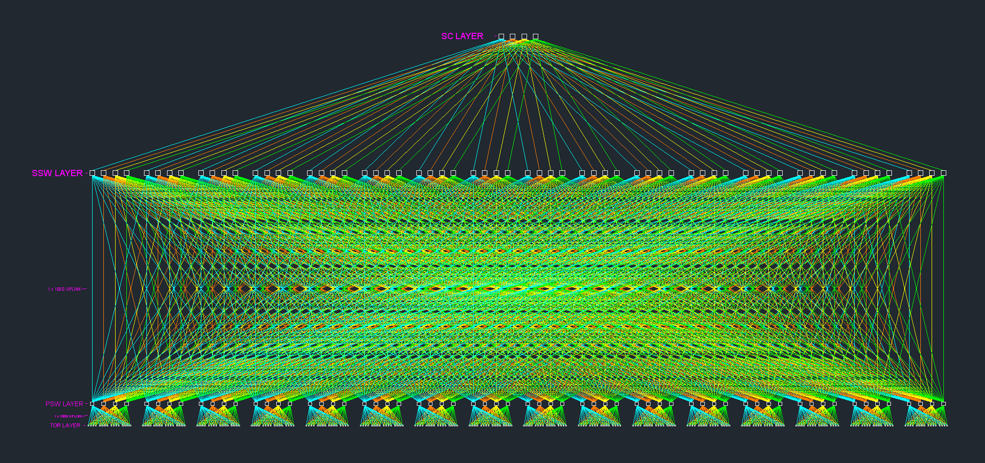
To support continued demand, we replaced this “four-post” architecture with a multi-tier, quad-plane fabric based on merchant silicon. We deployed the first fabric at a new California data center and have since scaled it to 16 pods.
Legacy architecture and its limits
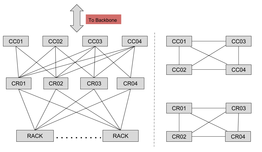
In the legacy data center, each cluster comprised one tier of rack switches and four chassis-based cluster router (CR) devices. The CR tier handled all intra-cluster traffic and served as the cluster’s gateway. Inter-cluster traffic passed through a second tier of four cluster connector (CC) devices, which also formed the data center’s single entry and exit point. All links ran at 100G.
We ran eBGP between the CC and CR tiers using private autonomous system numbers. Within a cluster, rack switches spoke iBGP to route reflectors. Devices inside the CC and CR tiers formed a full mesh, using ISIS as the IGP and iBGP over loopback interfaces. This worked well for years, but the port-density ceiling on each chassis made it hard to grow elegantly.
Design goals for the new fabric
We set out to fix the scaling limits while making the network simpler to operate. The key requirements:
- Support a larger number of racks than the legacy design
- Scale horizontally by adding capacity on demand
- Use a non-blocking fabric with stronger redundancy
- Eliminate chassis-based devices
- Use the same ASIC at every tier
- Keep every inter-switch link at 100G
- Offer multiple ECMP options at each layer
The three-tier, quad-plane fabric
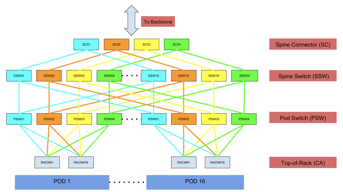
The fabric follows a straightforward three-tier design. Each pod holds up to 16 racks, connected to four pod switches (PSW). The PSW tier uplinks to 16 spine switches (SSW), which form the fabric core. A set of four spine connectors (SC) aggregates traffic leaving the fabric.
Every switch in the fabric uses the same merchant-silicon ASIC: a 1RU device with 32 ports of 100G and 3.2 Tbps of switching capacity. This consistency simplifies inventory, sparing, and configuration.
The fabric is not fixed in size. Pods are added incrementally as demand grows. A standard deployment supports 16 pods, but the design accommodates up to 31 pods—roughly 500 racks total. The limiting factor per plane is the number of spine-side ports reserved on each SSW. We allocated fewer ports for upstream traffic initially, so the number of pods can be expanded without a full redesign.
Failure domains are color-coded
Each device and interconnect in the fabric is assigned a color, which represents a distinct failure domain. Four colors exist, one per plane. A rack switch gets 4×100G of uplinks—one link per plane—so a loss of one plane drops 25% of rack throughput, leaving three paths intact.
Traffic planning is strict: a packet that enters a red link or device traverses only red links and devices until it exits the fabric. No traffic crosses between colors. This constraint applies both to rack-to-rack (east↔west) traffic and to traffic bound for networks outside the fabric (north↔south).
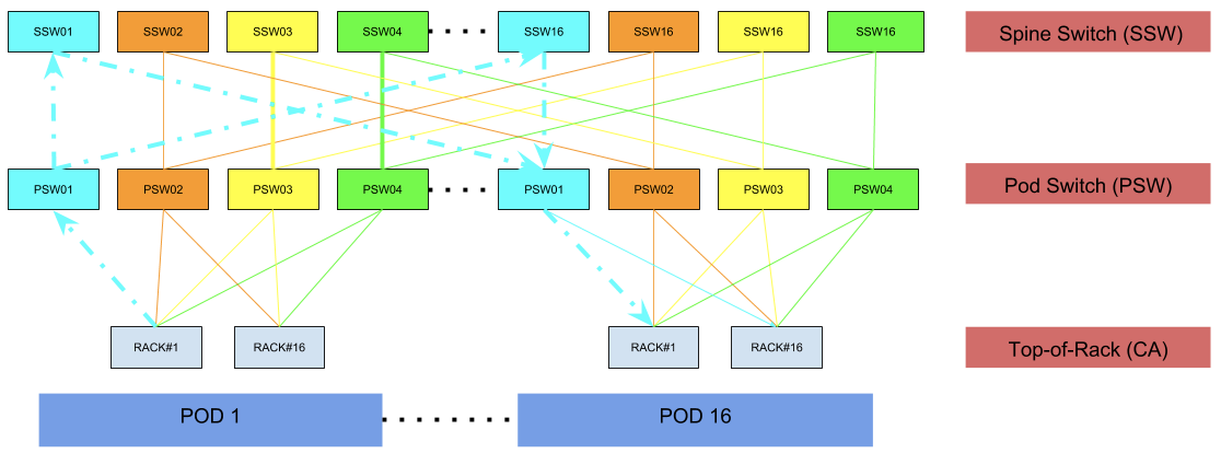
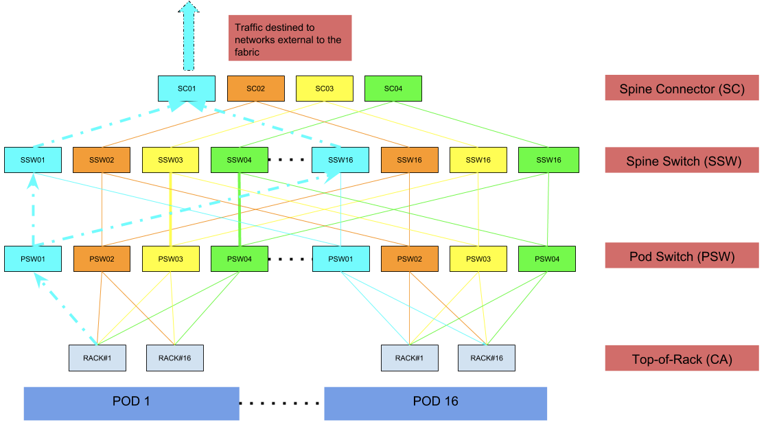
Each fabric plane carries 25% of total rack throughput. We can lose a full plane—one SC, 16 SSWs, and the identically colored host of PSWs—and the network remains healthy, though the remaining three planes must carry the load.
Cabling and physical layout
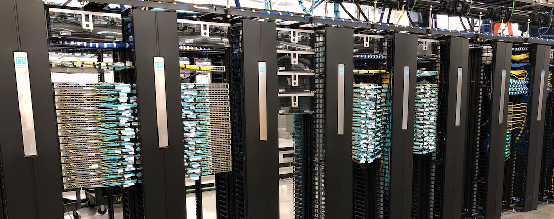
The number of interconnects runs into the thousands, before accounting for rack uplinks. Because all runs stayed within QSFP-100G-SR4 reach, we used that optic with MPO connectors over multimode fiber. The longest cable is about 140 feet, from the main distribution frame (MDF) to the farthest cabinet.
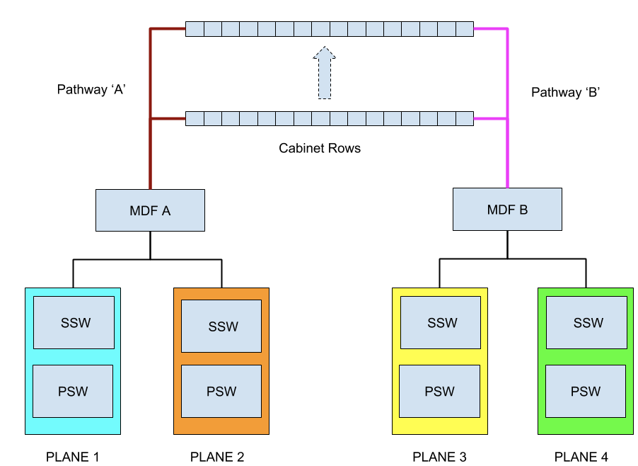
The design also builds in physical diversity. The four planes map across two MDF rows—labeled A and B. Each MDF row has its own redundant power distribution, protecting against electrical faults. Network pathways from each MDF to each cabinet are likewise separate, creating a physical failure boundary that aligns with the logical color domains.
Non-blocking with a 1:1 ratio
The fabric is wired non-blocking, with a1:1 oversubscription ratio between any two racks. Inputs equal outputs at each tier, so the network runs at full capacity from day one. Avoiding oversubscription also eliminates speed-mismatch problems and means we never had to split a 100G port to serve slower uplinks.
Routing and failure analysis
The fabric runs eBGP between every pair of devices. Compared with the legacy use of iBGP and route reflectors, eBGP simplifies operations and provides richer visibility into path selection via AS-path information. As before, the network is pure Layer 3 all the way to the rack switch, supporting both IPv4 and IPv6. Equal-cost multi-path routing with per-flow hashing distributes traffic evenly across all available links.
The failure characteristics differ by tier:
- Pod switch (PSW): Handles east↔west and north↔south flows. A failed PSW removes 25% of upstream capacity for that pod only, leaving the other pods unaffected.
- Spine switch (SSW): Handles both flow types. Each SSW connects to 16 PSWs and four SCs. Losing 1 of 16 devices in a plane affects only a 6.25% slice of capacity.
- Spine connector (SC): Handles only north↔south flows. With four devices in the tier, the failure of one SC reduces external capacity by 25%, but east↔west traffic is untouched.

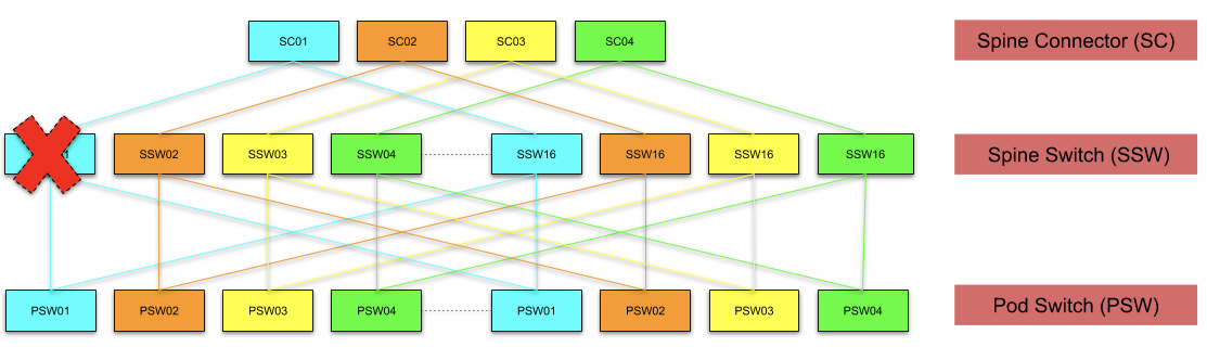

The highest-impact failure is a PSW loss, which degrades that pod to 75% uptime. That is still better than the legacy design, where any single cluster-level device failure would cut upstream capacity for every rack in the cluster by the same 25%.
Path to Higher Rack Counts
The current fabric architecture supports nearly 500 racks in a non-blocking configuration. Moving to an ASIC with greater port density, such as a 64×100G part, would quadruple that capacity while retaining non-blocking performance. As merchant silicon continues to increase in density, even larger fabrics become realistic.
Higher rack counts may force a fabric to stretch across multiple physical suites. That introduces a distance problem: the maximum reach of a QSFP-100G-SR4 optic would be exceeded. Options include parallel single mode 4-channel (PSM4) transceivers, coarse wavelength division multiplexing four-lane (CWDM4), or future specifications designed for connectivity across physically separated facilities.
The Network Engineering team is hiring engineers focused on Backbone, Datacenter, Edge, Optical, and related infrastructure work. Openings span a range of engineering roles in San Francisco, New York, Seattle, Tel Aviv, and other offices.
The rollout of the new design depended on close coordination across network engineering, network reliability engineering, cluster operations, supply chain, datacenter operations, finance, and technical program management.