Why the OSI Model Doesn’t Describe TCP/IP
Almost everything people call “networking” today really means the TCP/IP protocol suite — TCP, UDP, IP, ARP, ICMP, DNS, and friends. Yet most introductions to the subject start with the seven-layer OSI model. If you’ve ever felt that the OSI model’s layers don’t cleanly line up with real packets, you’re not misreading things. The OSI model is a generic reference framework, and its correspondence to TCP/IP is partial and often awkward.
The Layers That Do Map
The OSI model is an abstract description with seven numbered layers, from the physical layer up to the application layer. For the most commonly discussed protocols in the TCP/IP suite, a few of those layer numbers line up well with actual protocol headers:
- Layer 2 corresponds to Ethernet.
- Layer 3 corresponds to IP.
- Layer 4 corresponds to TCP, UDP, ICMP, and similar transport protocols.
- Layer 7 corresponds to the payload inside a TCP or UDP segment — for instance, a DNS query.
You can literally cut a packet open and assign one OSI layer number to each header section:
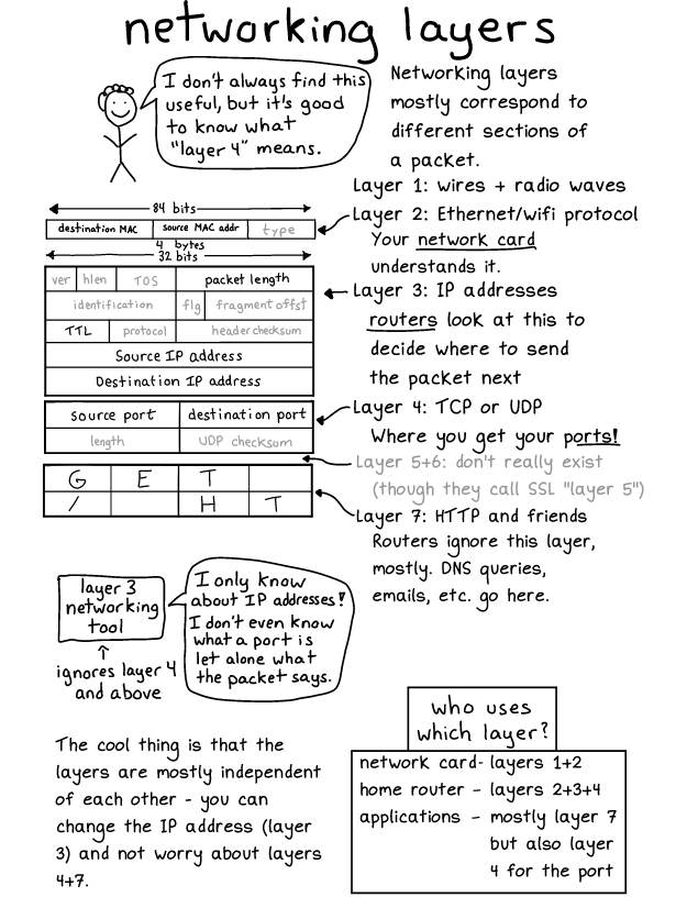
That works because each of those layers has a header of its own inside the packet. Practically every relevant protocol in TCP/IP fits into one of those four slots.
Why the Terms “Layer 2,” “3,” “4,” and “7” Still Matter
Even though the OSI model isn’t a precise blueprint for TCP/IP, you can’t avoid its vocabulary. The phrases “layer 2 routing,” “layer 4 load balancer,” and “layer 7 load balancer” are everywhere in technical documentation and product marketing. To read those materials, you need to know what the numbers mean — even if you wouldn’t choose those terms yourself.
In that sense, the OSI model is a shared jargon dictionary more than an accurate architecture diagram.
What About Layers 5 and 6?
Layers 5 (session) and 6 (presentation) don’t have a clear counterpart in TCP/IP. Various explanations exist — some claim TLS belongs at layer 6, others argue TCP itself collapses layers 5, 6, and 7 into one — but none of these mappings are as concrete as the header-for-header correspondence of layers 2, 3, and 4.
In practice you almost never hear anyone refer to layers 5 or 6 when talking about real TCP/IP traffic. The four layers that matter are the ones that appear as protocol headers: 2, 3, 4, and 7.
Protocols That Fit Nowhere
Even within layers 2–4, not every TCP/IP protocol fits neatly. ARP is the usual example. ARP solves the problem of discovering which MAC address owns a given IP address: a host broadcasts “who has 192.168.1.1?” and the owner replies “that’s me.”
ARP messages carry IP addresses, which suggests layer 3. But an ARP packet has no IP header — it’s an Ethernet header followed directly by ARP data. Since the common mental model for “layer 3” is “a packet with an IP header,” ARP doesn’t really satisfy that definition.
The mismatch isn’t an accident. The OSI model began as a description of a specific set of competing protocols from the 1970s and 1980s, during what’s now called the Protocol Wars. Those OSI protocols lost, and TCP/IP won. Had the OSI protocols won, the model would map perfectly onto the internet’s actual behavior. As it stands, the model fits the survivors imperfectly.
A Better Option: Just Name the Protocol
One way around the whole confusion is to stop using layer numbers entirely and name the protocol you actually mean. Instead of saying “layer 2,” say “Ethernet” or “MAC address.” Instead of “layer 7 load balancer,” say “HTTP load balancer” — every layer 7 load balancer in common use is an HTTP load balancer anyway, and if a device handled a different application protocol, you’d want to know which one.
For practical purposes, you can learn roughly how OSI layers 2, 3, 4, and 7 map to Ethernet, IP, TCP/UDP, and application payloads — then reasonably ignore the rest of the model. But when the model doesn’t fit, it helps to remember you’re free to skip the layer numbers and talk about the actual protocols on the wire.