Cape’s core architecture: more than a pipe
Cape is an event delivery system built for real-time asynchronous processing with strong guarantees. At its most basic level, it works as a pipe: event sources notify Cape when new events appear, and consuming topologies on the other end process them. But the implementation is far more involved than a simple queue.
Today Cape runs on thousands of servers, subscribes to over 30 event domains at roughly 30K events per second, processes jobs at about 150K per second, and delivers 95% of events to subscribers in under one second. More than 70 use cases rely on it across Dropbox.
Defining the event model
An event is persisted data identified by a two-part key: a subject (a string) and a sequence ID (an integer). Events sharing the same subject are strictly ordered by sequence ID, whereas events on different subjects are independent. A domain is a namespace for events constructed the same way.
A topology represents a user application. Topologies subscribing to the same domain can declare ordering dependencies—user-specified rules that force certain topologies to run before others. Within a topology, one or more lambdas do the actual work. Lambdas are callbacks invoked with batches of events; output from one lambda can feed input to another when processing the same event, enabling stage-wise data flow. Multiple lambdas per topology are valuable when stages naturally operate on data located in different data centers.
For each subject and topology, Cape tracks the last successfully processed event’s sequence ID as a cursor. Cursors for a subject are stored together in a single protobuf object called cursor info, keyed by the subject and persisted for retrieval.
Why a passive queue falls short
A naive design might place a queue at the center: sources publish events, topologies consume as independent groups. Cape rejects that model. Instead of receiving events, sources only send pings—lightweight notifications that a subject has new data. Cape analyzes those pings and issues jobs to workers. A refresh component also sends pings to handle backlog scenarios.
This design emerges from four requirements:
- Low latency: events must be delivered as quickly as possible.
- Retry until success: every event is eventually processed successfully by every subscribing topology.
- Subject-level isolation: a failure in one subject should not affect events in other subjects.
- Source reliability: external event sources can fail, and Cape must tolerate missed or delayed notifications.
Evaluating common queue systems—Kafka, Redis, SQS—against these requirements shows why none suffices on its own.
Low latency and durability tradeoffs
Kafka offers low-latency publishing and strong durability, and it can be deployed in-house. Redis is very fast when data lives only in memory, but configured for persistence via snapshots, availability suffers. For durability guarantees, both Kafka and SQS are solid; Redis is a maintenance burden when data must survive restarts.
Subject-level isolation is the dealbreaker
Creating a dedicated queue per subject is impractical—there can be billions. Using Kafka as a shared queue creates head-of-line blocking: each event must be acknowledged before the next is processed, so any slow or failing handler stalls every other subject’s events. Decoupling reads from acknowledgements lets consumers move forward, but a missed event forces a rewind that reprocesses all intervening, potentially large batches of unaffected subjects. That violates isolation.
SQS handles isolation elegantly with invisibility timeouts: a consumer picks an event, others can’t see it until a deadline, and acknowledgment removes it permanently. But ordered processing breaks down without FIFO mode, which imposes throughput limits. Even with ordered consumption achievable in theory, maintaining bookkeeping for which consumer owns which subject to preserve order is a custom service of its own.
Redis-based queues have a related flaw: consuming typically means removing, so a crash mid-processing loses the event. Peeking and deleting only after success reintroduces the same head-of-line blocking problem.
Sources can’t be trusted to publish everything
Event creation often rides the hot path of critical services—file sync or account signup, for example. If publishing to the event system fails, the rational production choice is to skip it rather than degrade the core service. Events therefore go missing from the source side. A queue-centric architecture that assumes reliable push simply cannot tolerate that reality, so Cape’s pull-based design with pings and its own cursor state is a deliberate workaround for distributed-system failure modes.
A Dispatcher Instead of a Queue
A queue built on SQS plus a bookkeeping service could work in principle, but Cape’s team needed something that scales without awkward custom accounting. Their answer is a dispatcher at the center of the scheduling architecture. Event sources don’t publish fully ordered events; they send lightweight, subject-related pings. That keeps the publishing workload on sources small and shifts scheduling complexity to one place.
Because the dispatcher handles all scheduling operations internally—no slow inter-server coordination—event delivery latency stays very low. The ping-based design also plays well with Cape’s refresh feature: every ping is tried at least once, so a lost ping eventually gets resent. Centralizing scheduling additionally unlocks advanced processing modes such as dependency-aware scheduling, ordered processing, and heartbeats.
How the Dispatcher Works
The dispatcher is Cape’s control plane, governing the full lifecycle of a scheduled job.
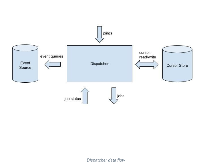
The flow is straightforward. An event source sends a ping for a subject. The dispatcher responds by querying the cursor store for the current cursor and pulling event information from the source. With those results it updates its in-memory state and decides which events go to which Lambda workers. Each batch of events is issued as a job with a unique job ID.
Workers report back with job status containing per-event results and the same job ID. On success, the dispatcher advances the cursor and may schedule further jobs if new work is triggered. The lifecycle for a ping completes when in-memory state shows no running jobs and nothing left to issue. If pings fail to arrive, the refresh component resends any that were lost.
Modular Internal Design
The dispatcher’s internals are built around modularity. Components have independent responsibilities and coordinate by message passing rather than shared memory. That keeps the communication protocol small and makes each piece individually testable.
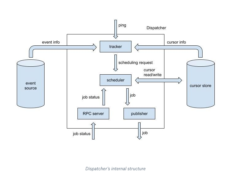
Four components make up the dispatcher:
- Tracker (stateless) — Receives pings and turns each into one or more scheduling requests for the scheduler. It queries the cursor store and event sources to make its decisions. Each request carries an event interval (a closed range of sequence IDs) plus the event set containing all events in that range.
- Scheduler (stateful) — The only component that writes to the cursor store and the sole owner of in-memory job bookkeeping. All its other operations are strictly in memory. It creates jobs from scheduling requests, sends them to the publisher, and handles job-status callbacks from the RPC server, deciding whether to issue more work.
- Publisher (stateless) — Receives jobs from the scheduler and places them into an external buffer that Lambda workers subscribe to.
- RPC server (stateless) — Takes job status reports from workers and forwards them to the scheduler.
This split follows a key observation about scheduling work: remote queries are expensive but stateless, while in-memory logic requires locking. The peripheral components handle the stateless queries and communication; the scheduler focuses on nearly pure in-memory scheduling decisions. Components run in parallel and coordinate through messages, which maps naturally onto Go’s concurrency model and keeps parallelism implementation straightforward.
How Request Scheduling, Failure Recovery, and Dispatch Work Together in Cape
While the high-level architecture explains how events flow between components, two lower-level mechanisms actually determine Cape’s behavior in production: the tracker’s event-query strategy and the scheduler’s in-memory state machine. Both play a central role in keeping the dispatcher stable when topologies lag or fail.
Tracker: Translating Pings Into Scheduling Requests
The tracker’s job is to convert an incoming ping for a subject into one or more scheduling requests. Each request carries the subject’s latest sequence ID, the event interval [sequenceId_start, sequenceId_target], and the set of events in that interval.
The sequence of operations is easiest to understand with an example. Suppose a ping arrives for subject S, and four topologies (T1–T4) subscribe to S. The tracker first fetches S’s latest sequence ID, which is 100, and then queries the current cursor positions for each topology:
- T1: 10
- T2: 90
- T3: 99
- T4: 99
With these positions known, the tracker issues event queries to retrieve events for scheduling. An event query takes a subject, a start sequence ID, and a maximum batch size, returning a capped, sorted list of events. The batch size is determined by the event source’s capacity and the data size of each event; in this example we assume a limit of 10. Note that an event range can only yield new jobs for a topology if it contains that topology’s cursor + 1.
Since event queries are expensive, both in latency and load on the source, the tracker asks a key optimization question: how can it make the fewest queries while still allowing every topology to progress as far as possible?
A naive solution would send one query per topology. That does not scale—the tracker’s work grows linearly with subscription count, and when topologies are mostly aligned, most queries just retrieve duplicate data. Cape’s first production heuristic grouped topologies by distinct cursor values. For the example above, that means three queries:
(S, 11, 10)(S, 91, 10)(S, 100, 10)
That approach worked well initially, when topologies ran simple, reliable processing logic. Problems emerged when expensive or flaky topologies were added. Longer execution times or frequent errors caused cursor positions to diverge. As more distinct cursor values appeared, the tracker’s worker pool saturated, delaying or canceling scheduling until the dispatcher fell into an unrecoverable, CPU-bound state.
The fix was to group cursor values by proximity—only one event query is issued per group. In the same example, this brings the query count from three down to two:
(S, 11, 10)(S, 91, 10)
This heuristic tolerates small cursor misalignment far better. A few unhealthy topologies no longer disproportionately affect the dispatcher, and the system has scaled cleanly to tens of topologies on a single event domain without sacrificing stability.
Scheduler: The Brain Behind Inflight Job Management
While the tracker is purely a producer of scheduling input, the scheduler is the single stateful component in Cape. It owns the “inflight state,” an in-memory structure that registers every job currently being executed or waiting to expire. It updates this state in response to new scheduling requests, job status updates, and timeouts, then issues decisions based on it.
The inflight state is composed of three parts.
State Tree
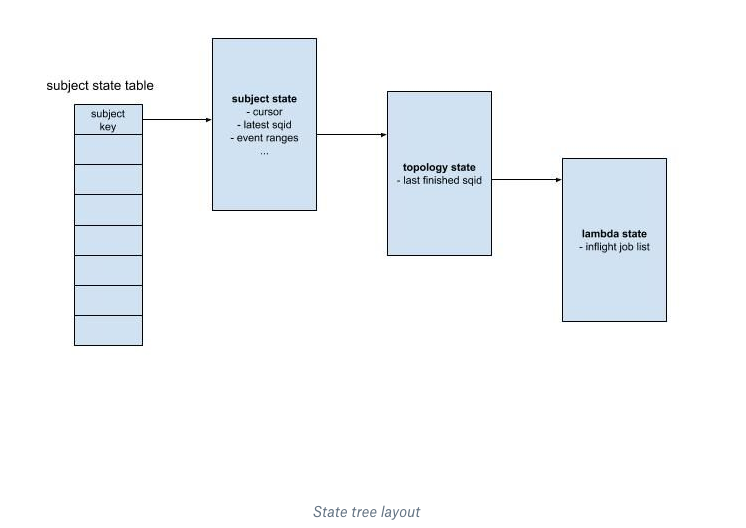
The first is a hierarchical tree for organizing scheduling information. At the root, a table maps each subject to its corresponding subject state. That node stores all shared information about the subject’s inflight jobs—cursor info, latest sequence ID, and the event ranges covered by those jobs. Below it, the subject fans out to one topology state per subscribing topology. At the leaves are lambda states, each holding a sorted list of inflight job records for that particular lambda.
Timeout List and Lookup Table
The second component, a timeout list, is a priority queue of references to all inflight jobs, ordered by expiration timestamp. The third is a job lookup table keyed by job ID. It holds job metadata used to locate job records in both the state tree and the timeout list.
Scheduling, Completion, and Timeout in Action
To understand how the algorithm behaves, consider two single-lambda topologies, T1 and T2, both subscribed to the same event domain. The scheduler receives a request for subject S with latest sequence ID 100, an event interval of [91, 100], and an event set [91, 99, 100].
Handling this request runs inside a Go routine. Before touching S’s subject state, the routine acquires a per-subject lock—this prevents race conditions in any concurrent access under that subtree. If the subject state doesn’t already exist, it’s created, and the routine queries the cursor store for current positions, finding T1 at 90 and T2 at 99. This fresh query is necessary even though the tracker just fetched the cursor because the tracker may have been operating on stale data; the scheduler could have moved cursors forward while the request was being prepared.
With the cursor values in hand, the subject state is updated with the request’s new event information. Topologies are then examined in a topologically sorted order based on their event dependencies. Comparing the [91, 100] range against each cursor shows T1 should receive events {91, 99, 100}, while T2 only has new events {100} available.
At the topology level, the scheduler selects which lambdas have work to do based on their dependencies. If a lambda already has a pending inflight job covering part of the range, the new job must only include events not yet covered. In this example, T1’s lambda already has a job on {91}, so a new job is created for the remainder: {99, 100}. T2’s lambda has no existing inflight job, so it receives a new job for {100}.
Once generated, each job’s record is appended to its lambda state. Job identifiers and expiration times go into the timeout list, and full metadata enters the job lookup table. When registration finishes, jobs are handed off to the publisher for dispatch.
Job Completion
When a worker finishes, it sends a job status update. The scheduler locates the job’s metadata in the lookup table, deregisters it, and removes the timer from the timeout list. It then locates the owning lambda state and marks the job successful. If no older jobs are still running for that topology, the cursor advances to the job’s last event—updating T2’s cursor from 99 to 100, for instance.
Job Timeout
The scheduler also periodically scans for expired jobs. Each expiration triggers essentially the same sequence as a job status update, except with a final step that marks the record as failed. If a job that covered events {99, 100} for T1 expires, that job is removed from the inflight state and labeled failed. The cursor is intentionally not advanced so that Cape can retry those events later.
This walkthrough intentionally simplifies a workflow that is substantially more intricate in practice. The state tree’s value is that it organizes information along a subject-to-topology-to-lambda axis. Every scheduling operation—request handling, job update, or timeout—enters at the subject level, passes down through the tree, and returns with post-processing at each layer. That hierarchical routing keeps scheduling logic modularized where a component-driven dispatcher would likely overload.
Design Takeaways
Cape's architecture reflects the realities of operating a large-scale distributed system: clear ownership boundaries, deterministic event processing, and careful separation of control flow from data movement. The dispatcher model keeps query routing and execution lightweight while delegating heavy state management to dedicated topology services, which gives the system flexibility to evolve components independently.
The event processing layer benefits from a strict ordering and idempotency discipline. By ensuring that every event carries enough context to be replayed safely, Cape avoids the feedback loops and partial-update hazards that often plague distributed systems. This makes the platform more predictable under load and easier to debug when behavior deviates.
Another key principle is being explicit about failure. Rather than masking errors with generic retries, Cape surfaces and classifies them at the boundary, enabling teams to act on root causes instead of symptoms. The result is a system that is both more resilient in production and more operable for the engineers who run it.
Building for Scale
We hope this look at Cape's design philosophy and inner workings conveys the range of challenges involved in building for large-scale distributed environments. The patterns behind Cape—clear contracts, deterministic processing, and explicit failure handling—are not specific to any one workload. They are generally useful when architects and engineers make trade-offs around consistency, availability, and operational complexity in their own systems.
No single system of this kind emerges from one person's effort. Many engineers contributed to Cape's design and implementation, including Anthony Sandrin, Arun Krishnan, Bashar Al-Rawi, Daisy Zhou, Iulia Tamas, Jacob Reiff, Koundinya Muppalla, Rajiv Desai, Ryan Armstrong, Sarah Tappon, Shashank Senapaty, Steven Rodrigues, Thomissa Comellas, Xiaonan Zhang, and Yuhuan Du.