Why a 3% failure can take down a data center
In 2017, an incident at Facebook's Forest City, North Carolina data center illustrated a subtle failure mode: a snake shorted a main switchboard power device, taking down 3 percent of the data center's capacity. The remaining 97 percent was untouched, yet user traffic still had to be redirected away from the entire facility. The problem was workload placement: the affected servers happened to host most of the capacity for several critical user-facing software systems.
This pattern repeated in other incidents. A fault affecting a small fraction of servers would, because of unlucky placement, force the loss of the data center's entire capacity as traffic was shifted away. Facebook's disaster recovery model assumes this full loss and maintains a spare data center as a buffer. But as the fleet grows, a more scalable approach is needed: survive the loss of a sub-data center fault domain without draining the whole facility.
Defining fault domains and buffer capacity
A fault domain is the amount of capacity that can be lost without causing wider problems. Each data center contains dozens of these domains, chosen based on the physical and logical design of the facility and the most common failure types observed in production. To tolerate losing one fault domain, the infrastructure must maintain enough spare capacity to absorb the loss; affected workloads would then move to that buffer. No traffic redirection would be required.
The amount of buffer needed depends on how workloads are placed within the data center. Workloads have heterogeneous hardware needs — high-compute, high-storage, or high-memory machines. If hardware and services aren't spread evenly across fault domains, the buffer must be larger to cover the worst-case loss.
A simplified model
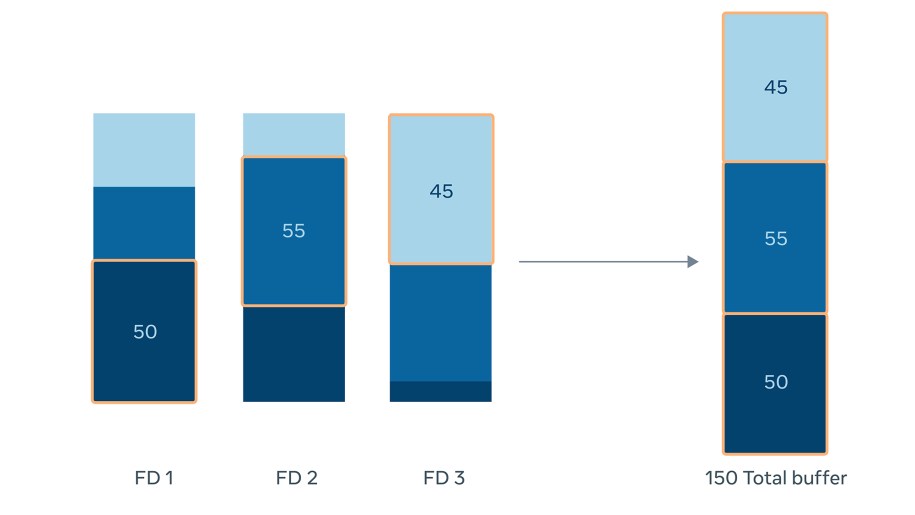
Consider three hardware types across three fault domains. When hardware isn't spread evenly, maintaining fault tolerance requires 150 buffer machines.
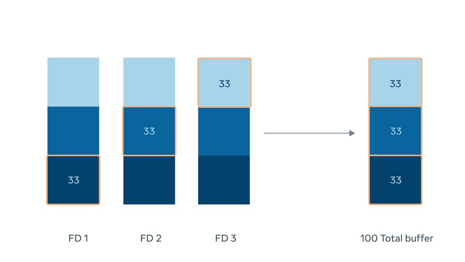
With the same hardware spread evenly across all fault domains, only 100 buffer machines are needed.
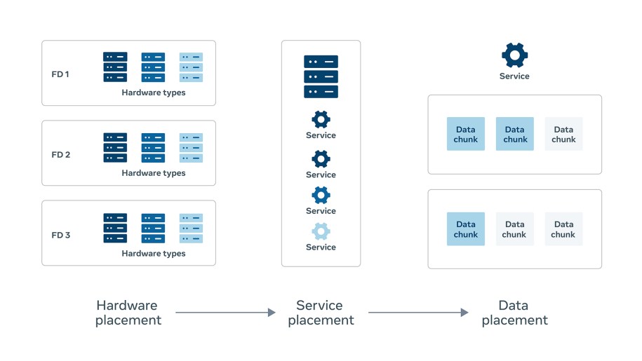 This approach requires solving placement problems at multiple levels of the infrastructure stack, with three guarantees:
- Hardware must be placed to give services enough flexibility for good spread.
- Services and workloads must be spread evenly across that hardware.
- For stateful services, spreading service instances isn't enough — the data shards must also be well placed, so a single fault domain doesn't concentrate too much data.
With one fault domain's worth of buffer and optimal placement across all levels, sub-data center faults can be tolerated without redirecting user traffic.
Hardware placement
Placement begins at the hardware layer. Data centers contain many rack types — compute, storage, flash/SSD — each serving different service classes. Each rack type must be spread evenly across as many fault domains as possible to give higher-level systems the flexibility to achieve their own spread.
Facebook's hardware capacity planning runs quarterly. Each quarter, the team determines how many racks of each type to purchase for each data center. Racks are placed into data halls, filling one hall before moving to the next; over a few years, the entire data center is cycled through. Placement decisions factor in data hall, row, and position, along with space, power, network, thermal effects, and spread across fault domains. With dozens of constraints per rack, integer linear programming systems compute the optimal plan.
Spread as a primary objective
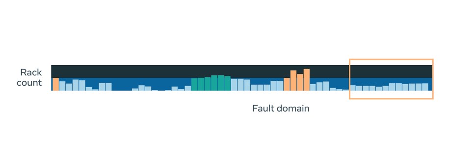
Even spread across fault domains is a critical objective because it enables tolerance of sub-data center faults. Incoming capacity is spread across all relevant fault domains in the data halls receiving racks that quarter, while other constraints are still satisfied. The diagram shows the difference in spread for one rack type before and after optimization.
Obstacles to even spread
Two main factors work against perfectly even hardware placement:
- Changing demand for capacity: Quarterly rack purchases follow service demand, which is uneven. One quarter may need more compute racks, the next more storage. Even spread can be achieved within a hall, but halls filled in different quarters end up with different distributions.
- Evolving data center designs: Facilities built at different times have different power hierarchies, network designs, and cooling infrastructures. Since fault domains may support different capacities, even spread becomes harder to achieve.
Rack moves for older capacity
New capacity can be placed optimally, but older halls and fault domains filled years ago were not built with these constraints in mind. To fix this, physical rack moves are performed. Systems compute which moves are needed, considering all current objectives and constraints. The moves require coordination across site teams performing the physical work, service owners draining racks of workloads, and teams building automation for data center processes.
Service placement
Well-placed hardware alone isn't sufficient — services themselves must be spread evenly across fault domains. This applies both to newly allocated capacity and to existing, older capacity that predates placement awareness.
Constraints on new service capacity
When service owners request additional capacity, placement systems weigh spread against other requirements. Two common constraints work against even distribution:
- Specific hardware requirements: Some services require not just a rack type but a particular CPU generation. If that generation only exists in a few data halls, the achievable spread is limited.
- Service affinities: Services that exchange heavy network traffic or need low-latency communication may be colocated within the same network domain. This reduces placement flexibility.
Continuous rebalancing
Older service capacity, allocated before placement was a consideration, is not evenly spread. Remediation requires hundreds of thousands of moves and swaps across fault domains. And this rebalancing is never finished: new halls come online, old capacity is decommissioned, and machines fail. Placement systems must watch for these changes and react to restore balanced placement across the active fault domains.
Sharding and Stateful Workloads
Even with bulletproof hardware and service placement, stateful services like blob storage or data warehouses have an extra layer of complexity: data. Spreading service instances evenly across fault domains accomplishes nothing if all the master shards or replicas for a dataset land in the same fault domain. Failures create two distinct strategies for these systems.
- Some services fail in place. They run their buffer capacity as part of normal operations, absorbing the loss of a single fault domain without any data migration. This requires careful, even spreading of shards so no single fault domain holds all replicas of a given shard.
- Other services migrate data to buffer capacity when a fault occurs. Rebuilding or moving data consumes expensive I/O and network bandwidth. In this case, the goal is to place shards to minimize the number of shards that need such heavy operations when a fault domain is lost.
Our centralized replica management system, Shard Manager, is fault domain aware. When it assigns shards to service instances, its algorithms maximize the spread of shards across fault domains, allowing stateful services to survive sub-data center faults without interruption.
Tolerating a Fault Domain Loss
Optimal placement of hardware, services, and data—paired with one fault domain’s worth of pre-allocated buffer capacity—lets workloads ride out sub-data center faults without any impact on users.
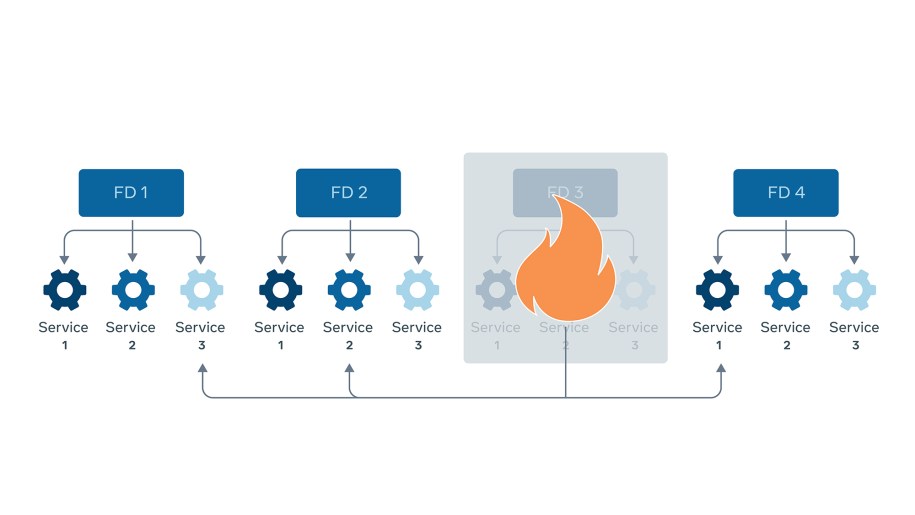 Consider services running across four fault domains. When FD3 fails, workloads under it immediately fail over to buffer capacity sitting in the other fault domains. Because that capacity is pre-provisioned and spread out, services don't need to request or provision new resources at the moment of failure. They simply continue serving traffic with minimal interruption.
Maintenance as a Failure
Abstracting resources away from workloads through optimal placement lets us provide infrastructure as a service and make operational processes more efficient. One of the biggest wins is in maintenance.
Maintenance covers any event that causes a loss of capacity—from physical repairs to software upgrades like kernel or firmware updates. In the past, this was a manual grind. To upgrade firmware on a top-of-rack switch, we'd have to contact every service owner running software on that switch, notify them of the maintenance window, and have them manually migrate their workloads to another rack.
With the fault tolerance enabled by optimal placement, we treat maintenance as just another sub-data center failure. Since we can survive the loss of any single fault domain, we simulate a failure and perform maintenance on all infrastructure under that fault domain at once. We then cycle through each fault domain, batching maintenance across all capacity in the domain. This makes data center maintenance predictable and significantly faster than the old manual process.
Beyond Even Spread
This placement strategy gives us strong assurances about how workloads run in our data centers without needing an entire spare data center’s worth of buffer capacity. But we are still early in the journey. The immediate goal is even distribution across fault domains, and the same systems can be extended to optimize other aspects of the data center. That includes reducing network bandwidth by factoring network domains into placement, avoiding thermal hotspots by keeping hot-running workloads from clustering, or stacking complementary workloads on the same machine for more efficient resource use.