A cheaper path from backbone to the last mile
Globally, more than 3.5 billion people remain offline, while average per-person data usage grows 20–30 percent each year. Mobile and wireline access networks have been upgraded repeatedly — from 2G/3G to 4G and beyond, and from DSL and coax to fiber to the home — but every one of those upgrades depends on fiber getting closer to the subscriber. The bottleneck is no longer the fiber itself; it is the cost of putting it in the ground or on poles.
Facebook Connectivity and its partners have spent several years developing an aerial fiber deployment system built around a robot that wraps a specialized fiber-optic cable onto medium-voltage (MV) power lines. The approach combines work in robotics and cable design to avoid the most expensive part of fiber construction. By riding on existing electrical infrastructure, the system eliminates much of the civil works that makes fiber deployment so costly, and it is designed to work on the MV grid that runs within a few hundred meters of much of the world’s population.
As of 2019, more than 70 percent of the world’s population lives more than 10 km from a fiber connection. The gap is acutely visible in rural and lower-income regions, where the electrical grid is often far more pervasive than any fiber footprint.
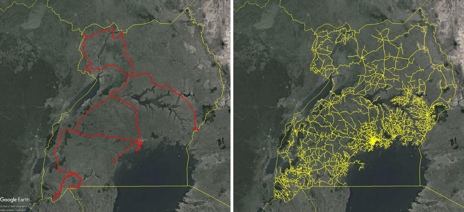
Technology trials of the deployment system are expected next year. NetEquity Networks has been named the first partner to deploy the technology, under a nonexclusive, royalty-free license from Facebook, which holds no financial stake in the company and will not own or operate the networks NetEquity builds.
Why power lines offer a way around make-ready costs
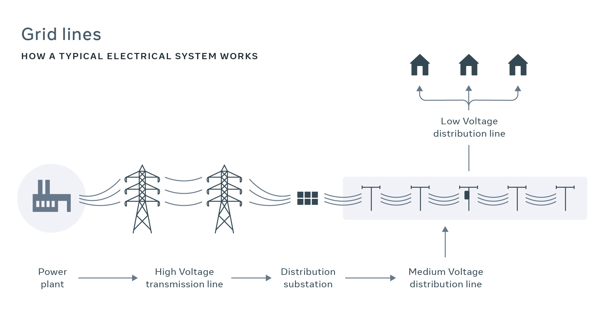
Electrical transmission grids move power from generation sites to substations on tall towers, much like a backbone. From substations, MV lines branch into communities, reaching homes and businesses more cheaply than any comparable fiber build. Because underground construction is significantly more expensive than aerial work, power infrastructure is almost exclusively aerial outside dense urban cores. Following that same grid with fiber is a natural way to build an end-to-end network.
Aerial fiber construction on existing poles normally sets off a chain of prep work: surveying pole loading, moving attachments, adding guy wires, and replacing poles. Combined, this make-ready work accounts for a large share of aerial construction cost. One operation that does not trigger that work is splicing a repair onto a broken power-line conductor. Repair splices weigh roughly one pound each, and utilities typically allow a few extra per line because the incremental load is negligible next to the conductor itself. That fact is irrelevant for conventional aerial fiber — but it is the key to a lesser-known installation method called helical wrap, or optical attached cable.
Helical wrap, adapted for distribution lines
Helical wrapping has been around since the early 1980s. A machine winds a fiber-optic cable around an existing power conductor rather than stringing a new, tensioned cable between poles. Because the fiber rides on the conductor, no new pole space is needed and no high-tension pull is required, which sidesteps the cost and delay of make-ready work.
The original wraps worked well on high-voltage transmission lines. A geared mechanism locked forward motion along the conductor to a rotating section that spun a spool of fiber and a counterweight around it. Forward movement came from a gas motor or a person pulling with a rope, and cranes or helicopters were needed to lift the machine past obstacles and to load or unload it. That approach was feasible on transmission grids, where obstacles are sparse and clearances are generous.
MV lines are a different matter. They run within a few hundred meters of most of the world’s population, but they present roughly ten times more obstacles per unit distance. The clearances around MV conductors are about an order of magnitude smaller, so a conventional spool cannot carry a useful amount of cable. The conductors themselves are thinner and weaker, limiting how much weight a wrapping machine, its cable, and its counterweight can add. Installation must also happen while the lines are energized, which means minimizing human contact.
The new deployment system is a MV helical wrap design that addresses those constraints. Its goal is a 3x to 5x reduction in aerial fiber construction cost, making it feasible to bring fiber within reach of rural and lower-income communities without the overhead of traditional builds — while keeping open access, fair pricing, and shared benefits with the electric utility as design goals for the resulting networks.
Design constraints that shaped the system
For helical wrap to be economical in the medium-voltage (MV) space, the continuous length of fiber that can be deployed between splices is a critical driver. Fusion splicing is slow and expensive, so the practical minimum is determined by pairing two machines traveling in opposite directions, each carrying connected back-to-back reels. That makes the maximum splice spacing twice a single robot's cable capacity. To accommodate the thinnest power-line conductors, the team settled on a minimum cable capacity of just over one kilometer per robot.
Outdoor fiber cable is only a few millimeters larger in diameter than indoor cable, but a kilometer of it weighs more than 10 times as much. The conventional wisdom on cable diameter stems from strand count: a single fiber carries roughly 53,000 GHz of bandwidth, more than enough for an entire region. But optical link budgets restrict how many times a signal can be split before insertion and splitter losses become prohibitive, which caps the number of endpoints per fiber. Since construction costs dwarf the cost of the fiber itself, and route demand is hard to predict, networks are typically built with substantial overprovisioning.
An MV grid route changes that math. A fiber cable following a feeder never passes more homes than the feeder was designed to serve—typically a few thousand, though in developing countries that can reach 15,000. With carefully selected optical components, a 24-strand cable can support a wholesale lit service for all of those premises. Twenty-four strands also allows a single loose tube instead of the usual four or more, shrinking the cable's core.
Using the MV line as a support introduces stress beyond what a typical outdoor cable sees. Conductors may operate at up to 35 kV, inviting tracking, partial discharge, and dry band arcing. Elevated conductor temperatures can exceed the melting point of standard fiber jackets, and thermal cycling plus wind-induced aeolian vibration can strain the fibers. Veteran cable designer Wayne Kachmar was brought in to address these conditions. Working with partner companies and academic advisors, the team developed a design using G.657 200-micron fibers, a specifically tailored aramid configuration, and a high-strength, high-temperature, track-resistant polymer jacket—all in a small form factor.
Even at a 4 mm outer diameter, cable volume and counterweighting caused problems. A conventional helical wrap pays cable off a standard spool as it orbits the conductor, but a spool sitting offset from the conductor is limited by available clearance in flange diameter and spool height. That meant it could not carry the required fiber—even with the reduced cable diameter. The offset spool's center of gravity also demanded a counterweight, which further consumed the wrap machine's weight budget.
The solution took years and dozens of approaches, from spools with driven surfaces to curved and multi-axis mandrels. The final design resurrects and upgrades a technique originally developed for military applications: it eliminates the spool entirely. A spool-free cable coil geometry meets all clearance requirements around the conductor, allowing the machine to pass obstacles while keeping the center of mass aligned within 2 mm of the power line's center—removing both spool and counterweight.
The robot and live-line operation
The wrapping machine itself presented the final major hurdle. Bare overhead MV conductors rely on clearance to prevent arcing, but a century of diverse utility standards means a vast range of support structures, insulators, and taps. The common thread across all those standards is the goal of preventing electrical hazards, so obstacle navigation requirements can be distilled into one consistent but demanding specification.
Chief among them: the fiber must be installed while the conductors are energized, since extended outages would disrupt the very homes and businesses the network aims to serve. That forces the wrapping machine to cross every obstacle autonomously, with no human intervention. After consultations with robotics companies worldwide, ULC Robotics was selected for its concept design and its decade-plus of experience in high-reliability utility robotics.
ULC's design splits the machine into drive, lift, and rotation subsystems. The drive subsystem consists of a pair of driven grippers that move relative to each other to handle obstacles and conductor angles. To clear an obstacle, the lift subsystem raises the payload and rotation subsystems from their normal wrapping position—center of mass aligned with the power line—up and over. In this raised state the robot is unbalanced, like a tightrope walker, and uses a stabilizer to stay upright while crossing. Once past, the payload and rotation subsystems lower and wrapping resumes.
The robot carries a vision system that identifies obstacles and adjusts its movements accordingly, maintaining the clearances required to prevent electrical hazards. Weight and material properties are currently being optimized for safe operation on live lines.
Deployment economics and productivity
Each robot installs over a kilometer of fiber in about an hour and a half, passing dozens of obstacles autonomously in that time. Including human steps like setup, loading, unloading, and transitions, the team conservatively estimates 1.5 to 2 km of build per robot per day.
Traditional aerial fiber deployment requires heavy machinery, reel carts, large spools, and sizable crews. This system needs just two or three electric utility linemen with a pickup truck carrying a few kilometers of fiber, the robot, and accessories. Quanta Services developed an apparatus that lets line staff safely load and unload the robot from the live line. There is also a custom cable clamp for periodically attaching the fiber to the power line using a hot stick, plus a specially designed splice case and phase-to-ground assembly. Total estimated cost, including labor, depreciation, and materials, is $2 to $3 USD per meter in developing countries.
Lowering the total cost of aerial fiber is expected to affect internet penetration, particularly among the roughly half the global population earning less than $5.50 USD per day. Because each fiber strand carries enormous bandwidth, capacity upgrades come from swapping electronics at each end rather than rebuilding the physical plant. That yields a cost-per-bit curve that falls over time, even as capacity climbs.
Before first deployment, several milestones remain—along with close coordination with electric utilities, since the approach depends on critical utility infrastructure. The team notes that fiber also offers communication benefits to utilities themselves for operational use. With that cooperation, the technology is aimed at enabling large-scale fiber rollouts worldwide, with abundant capacity driving lower consumer prices. The effort acknowledges the contributions of Robert Olding, James Mass, Richard Ahlschlager and his team at Aurecon/Zutari South Africa, Greggory Bell and his team at Quanta Services, Carlos Vera, and manager and mentor Yael Maguire.